DC solid-state power switch circuit

A technology of solid-state power switches and main power circuits, applied in electronic switches, electrical components, pulse technology, etc., to achieve low power consumption, suppress peak voltage, and simple and reliable driving circuits

Active Publication Date: 2005-09-14
SHANGHAI AVIATION ELECTRIC
View PDF0 Cites 40 Cited by
  • Summary
  • Abstract
  • Description
  • Claims
  • Application Information

AI Technical Summary

Problems solved by technology

[0014] Short-circuit protection is a necessary protection function for solid-state switches to work reliably. Short-circuit is the worst fault in the system. It is required that the solid-state switch must be able to deal with short-circuit faults in a very short moment (25μs), cut off the circuit, and protect the load and the circuit from damage. , and

Method used


Image

  • DC solid-state power switch circuit
  • DC solid-state power switch circuit
  • DC solid-state power switch circuit

Examples


Embodiment Construction

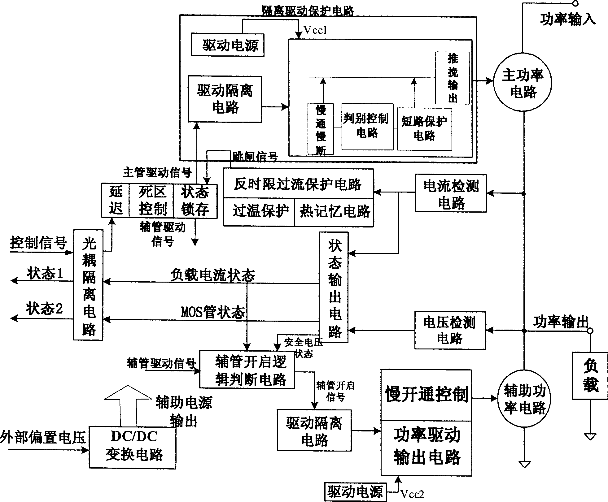
[0036] figure 1 The basic schematic diagram of the DC solid-state power switch circuit is given. The power input is a DC voltage (600V>Uin>36V), and the host computer issues control commands to control the drive circuit to control the on and off of the main power tube. The detection circuit is connected in series in the main power circuit to sample the load current, amplify the sampled current for judgment and comparison, so as to realize inverse time overcurrent protection and load current detection, and the trip status signal of the overcurrent protection is output to the drive circuit It is used to turn off the main power tube and output the load current state to the host computer. The output voltage is sampled at the power output terminal, and the state detection and safety voltage detection of the main power transistor MOSFET are realized by judging and comparing the output voltage. Under the action of the dead-zone control circuit, when the main power tube is turned of...


PUM


Abstract

A DC solid power switch circuit includes a main power circuit, a subsidiary power circuit parallel to the load, an isolated drive protection circuit composed of a drive supply, a drive isolation circuit, a slow turned-on-off control circuit, a discriminating control circuit, a short circuit protection circuit and a push and pull output circuit, a current detection circuit, a voltage detection circuit, a main power valve drive circuit, a light-coupled isolating circuit, an assistant power valve switch-on logic circuit and a power drive output circuit, which can limit the current impulse in the period of switching on capacitive load, and suppress the peak voltage in turning off the inductive load.

Description

[0001] Technical Field The present invention relates to a DC solid-state power switch circuit, which belongs to the field of power electronics and electrotechnical technology Background technique [0002] The specific implementation of the DC solid-state power switch circuit involves the following key technologies: [0003] 1. How to solve the problem of the peak voltage at both ends of the switch tube when the inductive load is turned off and the accumulated voltage caused by the leakage current of the power tube in the actual circuit. [0004] 2. Realization of inverse time overcurrent protection circuit [0005] At present, there are mainly logarithmic index method and curve fitting method in the realization of the analog circuit of inverse time overcurrent protection. The disadvantage of the two methods is that the realized inverse time characteristic overcurrent protection curve has large error and low precision. [0006] 3. Thermal memory function of the circuit [000...

Claims


Application Information

Patent Timeline
IPC IPC(8): H03K17/00H03K17/08
Inventor 王莉王志强严杰杨善水严仰光
Owner SHANGHAI AVIATION ELECTRIC
Why Eureka
Try Eureka