Supercharge Your Innovation With Domain-Expert AI Agents!

Method and system for frequency hopping radio communication

A wireless communication system and wireless communication technology, applied in the field of frequency hopping wireless communication, can solve problems such as difficult and expensive stabilization devices

Inactive Publication Date: 2005-09-14
NAT INST OF INFORMATION & COMM TECH
View PDF0 Cites 3 Cited by
  • Summary
  • Abstract
  • Description
  • Claims
  • Application Information

AI Technical Summary

Problems solved by technology

In addition, since the frequency changes suddenly, it is necessary to respond at a high speed accordingly
However, it is usually very difficult to realize a frequency-hopping synthesizer capable of such high-precision frequency synchronization, such as at frequencies as high as the millimeter wave band, and at the same time, in the case of large frequency deviations, immediate response or synchronous supplementation is a must. Difficult, to overcome this difficulty the system has to be equipped with very expensive stabilization devices

Method used


Image

  • Method and system for frequency hopping radio communication
  • Method and system for frequency hopping radio communication
  • Method and system for frequency hopping radio communication

Examples


Embodiment 1

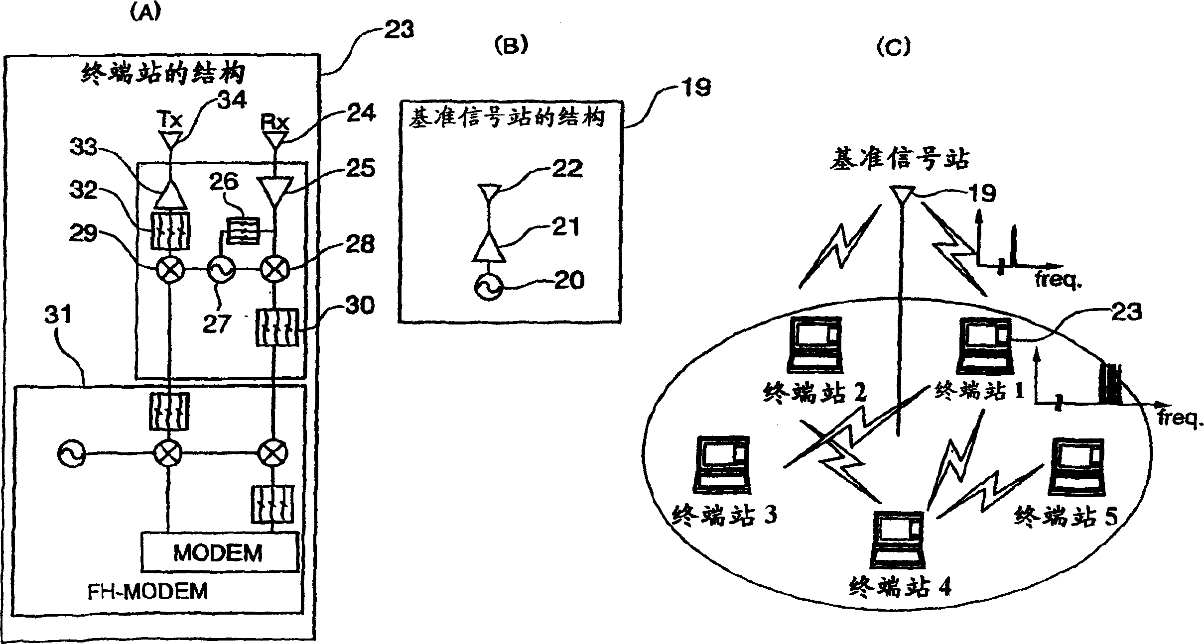
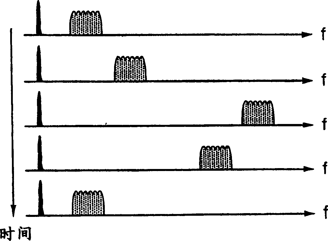
[0018] figure 1 Indicates the structure of the wireless communication system according to Embodiment 1 of the present invention, figure 2 Indicates how the spectrum of the signal transmitted / received by each station changes. Such as figure 1 As shown in (C), the system is composed of one reference signal station 19 and a plurality of terminal stations 23 . Such as figure 1 As shown in (B), the reference signal station 19 amplifies the reference local oscillation signal generated by the reference local oscillator 20 through the amplifier 21 and transmits it to the service area through the antenna 22 . Such as figure 1 As shown in (A), each terminal station 23 receives through the receiving antenna 24 . After the received signal is amplified by the amplifier 25 , part of it is branched, unnecessary radio waves are removed by the band-pass filter 26 , and then input to the injection synchronous oscillator or the amplifier 27 . As a result, a local oscillation signal sy...

Embodiment 2

[0025] image 3 and Figure 4 Showing the structure of the transmitter and the structure of the receiver of the wireless communication system according to Embodiment 2 of the present invention, Figure 5 Indicates the changes in the spectrum of signals sent / received between terminals at this time. The present invention can be used for communication between multiple wireless terminals, and each wireless terminal is equipped with image 3 The sending section of the structure and the adoption of Figure 4 structure of the receiver, so it is possible to communicate in both directions.

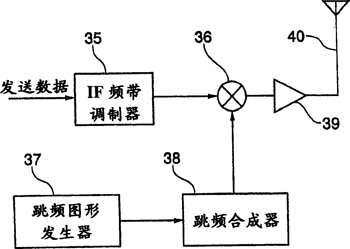
[0026] image 3 In the illustrated transmitter, the transmission data passes through the IF frequency band modulator 35 to generate an IF modulated signal, and the FH signal obtained by the frequency hopping synthesizer 38 controlled by the frequency hopping pattern generator 37 and the IF frequency band modulated signal are input to the mixer, Thus, a frequency-hopping wireless signal is obta...


PUM


Abstract

A transmitter inputs an IF band modulation signal generated from transmission data and a frequency hopping signal acquired by a hopping synthesizer controlled by a hopping pattern generator to a mixer to acquire a radio signal with a hoping frequency and to transmit it. A receiver inputs an amplified reception signal from which the unwanted wave is removed and an output signal from the hopping synthesizer controlled by a signal produced by adding a fixed frequency offset signal to a hopping pattern generator to the mixer, downconverts the input signal to an unhopping IF band corresponding to the offset signal while maintaining the relative spectral relationship of the signal in the radio frequency band and acquires required data by demodulating an IF band modulation signal regenerated through unwanted wave removal and square-law detection.

Description

technical field [0001] The present invention relates to a frequency hopping wireless communication method and system when performing wireless communication using a frequency hopping method in a very high frequency area such as a millimeter wave band. Background technique [0002] When establishing a wireless communication system used in a license-free frequency band, it is effective to adopt a frequency hopping method as a means for avoiding or sufficiently suppressing the influence of narrowband interference. [0003] Image 6 and Figure 7 Shows the configuration of the receiver and the configuration of the transmitter of the wireless communication system when a normal frequency hopping method is used. The signal obtained from the intermediate frequency (IF) band modulator that inputs the transmitted data, and the output of the frequency hopping synthesizer 3 controlled by the signal from the frequency hopping pattern generator is input to the mixer 4 by the transmitter, ...

Claims


Application Information

Patent Timeline
Patent Type & Authority Applications(China)
IPC IPC(8): H04B1/713H04B1/7136H04J11/00H04W56/00H04W72/04H04W76/02
CPCH04B1/7156H04B1/713
Inventor 荘司洋三小川博世
Owner NAT INST OF INFORMATION & COMM TECH
Features
  • R&D
  • Intellectual Property
  • Life Sciences
  • Materials
  • Tech Scout
  • Unparalleled Data Quality
  • Higher Quality Content
  • 60% Fewer Hallucinations
Learn More