

Clutch disengagement bearing
A technology for separating bearings and clutches, applied in clutches, bearings, mechanical drive clutches, etc., can solve the problems of increased wear, friction and rust, and can not achieve the service life of automobile manufacturers, reduce bearing load, ensure high temperature resistance, The effect of improving emergency operation performance
- Summary
- Abstract
- Description
- Claims
- Application Information
AI Technical Summary
Problems solved by technology
Method used
Image

Examples
Embodiment Construction
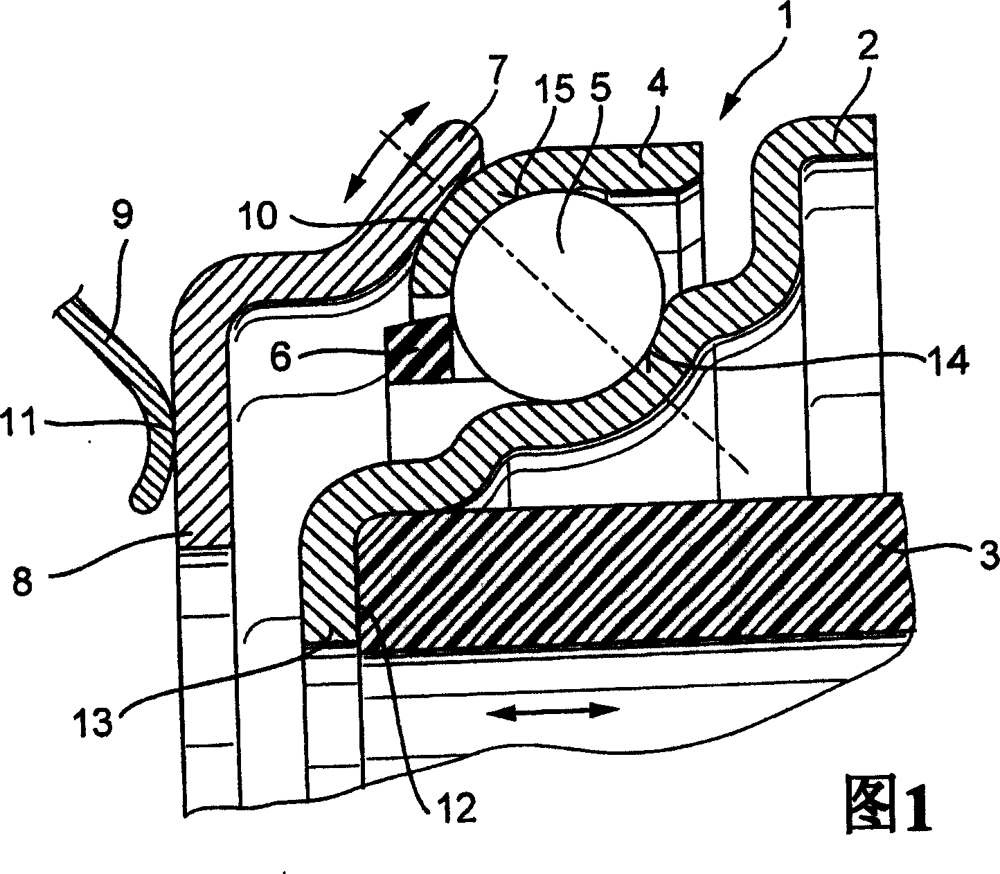
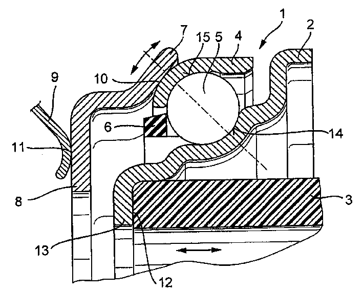
[0031] FIG. 1 shows the release bearing 1 in the mounted state. In this case, the inner bearing ring 2 is connected in a rotationally fixed manner to an actuating device 3 which surrounds a transmission shaft (not shown in FIG. 1 ), which connects the internal combustion engine to the gear transmission. For coupling and decoupling, the handling device 3 is axially movable as indicated by the double arrow. Rolling bodies 5 arranged at a distance in a cage 6 are guided between the inner bearing ring 2 and the associated further outer bearing ring 4 . On the outer side of the outer bearing ring 4, an adjusting ring 7 is mounted, which forms a radially inward ring flange 8, on which a spring element 9, in particular a disk spring, of the transmission clutch is supported with appropriate force. As a result of this arrangement, both the adjustment ring 7 and the outer bearing ring 4 are set in rotation with the transmission separation clutch. In order to compensate coupling shocks...
PUM
 Abstract
Description
Claims
Application Information