
Inductive magnetic head with non-magnetic seed layer gap structure and method for the fabrication thereof

一种非磁性、磁头的技术,应用在带金属薄板芯的磁头、使用薄膜的磁头、磁记录头等方向,能够解决不利等问题,达到增大面数据存储密度的效果

Inactive Publication Date: 2005-10-05
HITACHI GLOBAL STORAGE TECH NETHERLANDS BV
View PDF0 Cites 6 Cited by
  • Summary
  • Abstract
  • Description
  • Claims
  • Application Information

AI Technical Summary

Problems solved by technology

In this case, the relatively ordinary magnetic properties of the magnetic seed layer are unfavorable for the required magnetic flux flow through the P2 pole tip

Method used


Image

  • Inductive magnetic head with non-magnetic seed layer gap structure and method for the fabrication thereof
  • Inductive magnetic head with non-magnetic seed layer gap structure and method for the fabrication thereof
  • Inductive magnetic head with non-magnetic seed layer gap structure and method for the fabrication thereof

Examples


Embodiment Construction

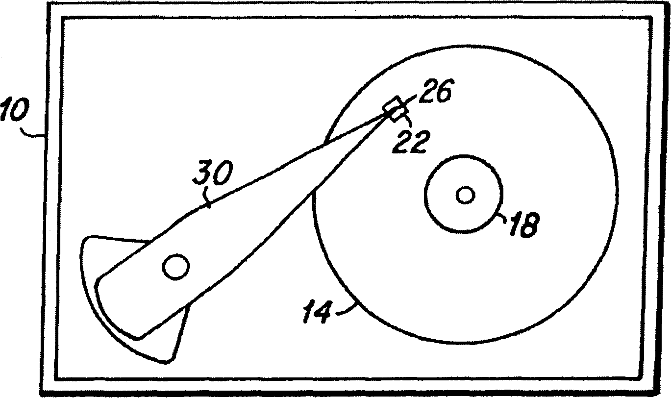
[0020] exist figure 1 A simplified top view of a typical hard disk drive 10 that includes the magnetic head of the present invention is shown in FIG. As shown, at least one hard disk 14 is rotatably mounted on a motorized mandrel 18 . The slider 22 on which the magnetic head 26 is disposed is mounted on the actuator arm 30 to fly over the surface of each rotating hard disk 14, as is known in the art. The present invention includes improved features and methods of manufacture for such a magnetic head, and prior art magnetic heads are described below for a better understanding of the present invention.

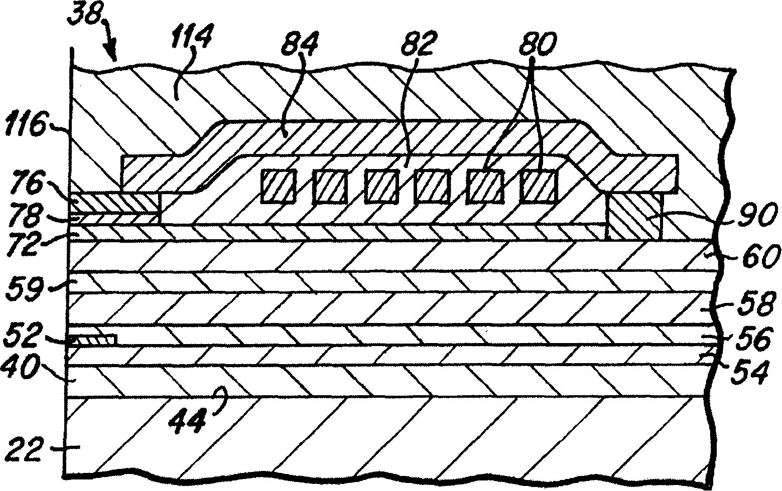
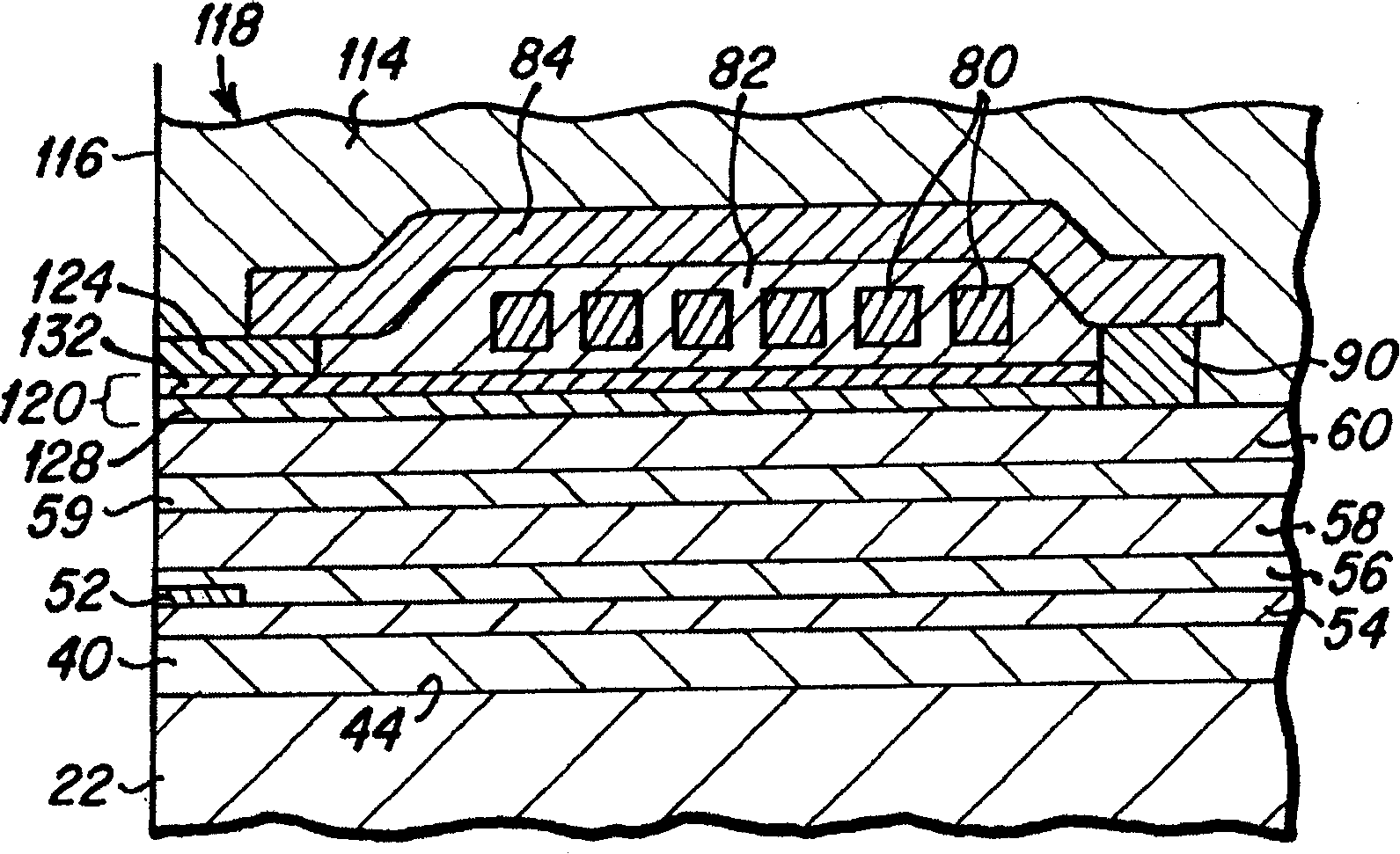
[0021] As understood by those skilled in the art, figure 2 is a side cross-sectional view depicting portions of a prior art magnetic head, which is referred to as a longitudinal head. like figure 2 As shown, the magnetic head 38 includes a first magnetic shield layer ( S1 ) 40 formed on the surface 33 of the slider body material 22 . Readhead sensor element 52 is disposed...


PUM


Abstract

The present invention discloses a magnetic head, including a first and a second magnetic pole, and a write gap layer placed between the two poles. In the first embodiment, the write gap layer includes a non-magnetic, non-conductive first layer, which is preferably composed of Ta or Ti, and deposites on the first pole as the role of a bonding layer. The write gap layer further includes a second layer layer, which is formed by a non-magnetic, non-conductive material, preferably composed of Rh or Ru. The P2 pole sharp is plated on the second layer, in which the conductive second layer is used to conduct the plating current. In another embodiment, the write gap layer includes a third layer, which can be etched in an active ion etching (RIE) process, and is formed between the first layer and the second layer. The third layer is preferably composed of Ta or Ti.

Description

technical field [0001] The present invention relates generally to a magnetic head for a hard disk drive, and in particular to the manufacture of a non-magnetically inductive write gap between the poles of the write head portion of such a head. Background technique [0002] As known to those skilled in the art, standard magnetic heads include a write head element comprising two poles, commonly referred to as a first pole (P1) and a second pole (P2), where A write gap layer is formed therebetween. During data recording, the magnetic flux crosses the write gap between the two magnetic poles to generate a magnetic field. This magnetic field affects the thin film layer of the magnetic medium on the hard disk located near the magnetic head, causing the changing magnetic flux to form data bits in the magnetic medium. . In a longitudinal magnetic head, the size of the data bits is substantially determined by the size of the pole tip of the second pole, which is referred to herein ...

Claims


Application Information

Patent Timeline
Patent Type & Authority Applications(China)
IPC IPC(8): G11B5/147G11B5/187G11B5/23G11B5/235G11B5/31
CPCY10T29/49046G11B5/313G11B5/235G11B5/3116G11B5/187
Inventor 阿普里尔·D·希克森-戈德史密斯杰弗里·S·利勒
Owner HITACHI GLOBAL STORAGE TECH NETHERLANDS BV
Learn More