Gravity engine roller skating boots and walking electric power generator

A technology of engines and roller skates, applied in the field of walking power generation devices, to achieve the effect of efficient use of energy

Inactive Publication Date: 2005-10-12
关慎捷
View PDF0 Cites 3 Cited by
  • Summary
  • Abstract
  • Description
  • Claims
  • Application Information

AI Technical Summary

Problems solved by technology

[0004] Another object of the present invention is to overcome the deficiencies in the prior art, to provide a kind of roller skates using the above-mentioned gravity motor, so that the roller skates can be used closer to natural walking, and not only can the energy wasted during walking be converted into useful energy , so that the problem of uphill can be solved

Method used


Image

  • Gravity engine roller skating boots and walking electric power generator
  • Gravity engine roller skating boots and walking electric power generator
  • Gravity engine roller skating boots and walking electric power generator

Examples


Embodiment Construction

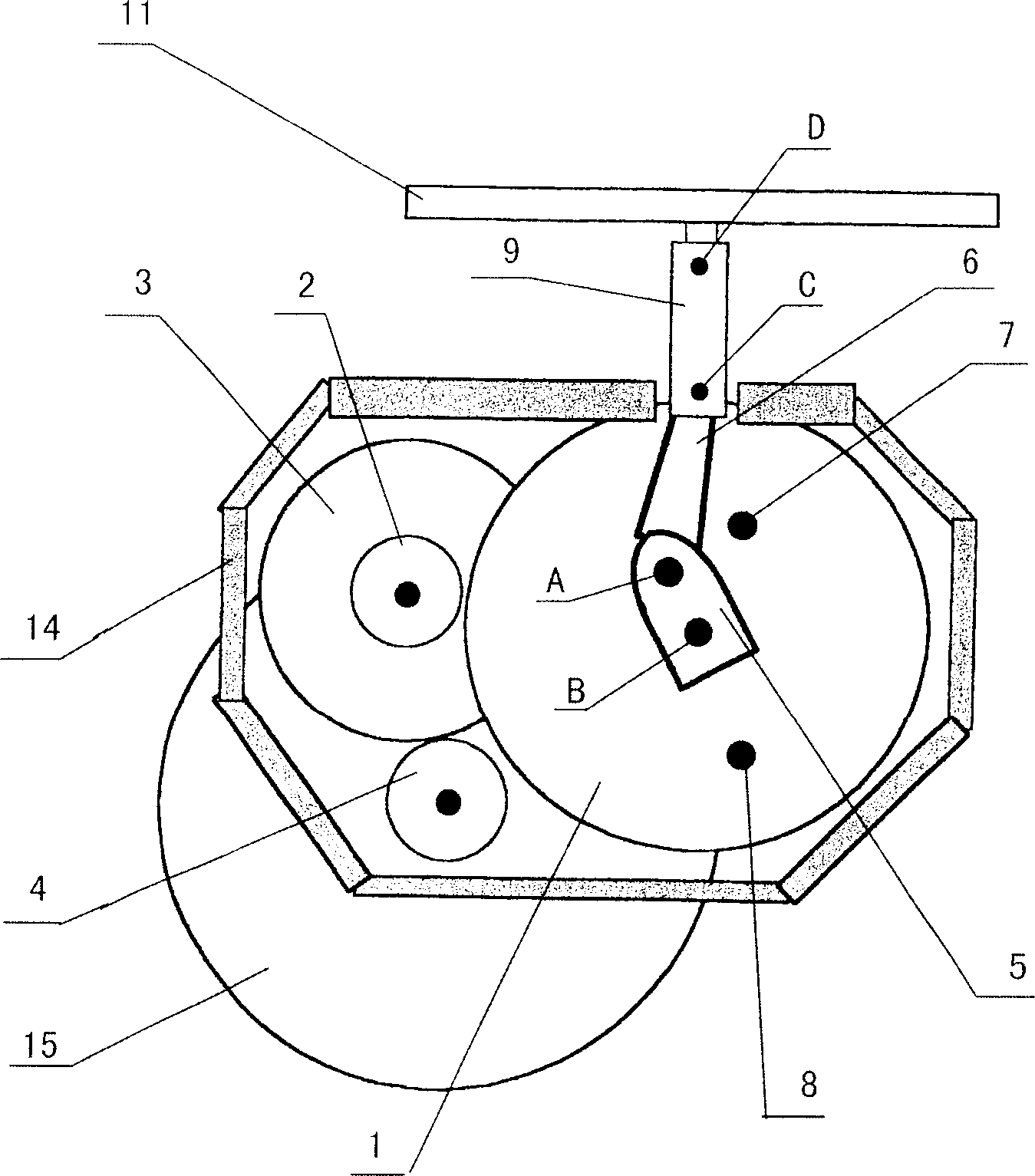
[0031] Such as image 3 , Figure 4 , Figure 5 As shown, the gravity engine described in the embodiment of the present invention includes a rotatable pedal 11, a piston 9, a connecting rod 6, a crankshaft 5, an upper gear lever 7 and a lower gear lever 8, wherein the upper gear lever 7, the lower gear lever 8 are arranged on the side wall of the gearbox 13 near the upper and lower positions respectively, and are used to limit the rotation range of the crankshaft 5 between an upper limit position and a lower limit position. The piston 9 transmits downward pressure, and the piston 9 is also equipped with a piston spring 10 to help the piston 10 return to the upper limit position when the pressure is released. Such as image 3 As shown, the engine is also provided with a piston upper soft case 16 . The connecting rod 6 is connected with the piston 9 through C and connected with the crankshaft 5 through the axis A of the crankshaft 5, and the crankshaft 5 rotates around its a...


PUM


Abstract

This invention is a gravity driving small motor and a roller skates driving by the motor. The motor is designed to convert the gravity energy from moving body during rolling to dynamical power for the roller skates. The motor can be fixed to the bottom of the roller skates or fixed to the shoes in this case the shoes can generate electricity.

Description

technical field [0001] The invention relates to a power device, in particular to a gravity motor, a roller skate using the gravity motor and a walking power generation device using the gravity motor. Background technique [0002] As we all know, when people walk, they need to lift their legs and raise their center of gravity to resist gravity. When the foot falls back to the ground, this part of the energy is absorbed by the ground and the sole in a deformed manner, and almost all of it is wasted. At present, there is no power plant that can effectively utilize the energy in the prior art. For example, gravity engines and walking generators that can effectively utilize the energy. On the other hand, roller skates have been around for decades and have been widely used in physical exercise and other activities for many years. As its name suggests, roller skates are modeled after skates, both in appearance and in use, and are suitable for horizontal and smooth surfaces with ...

Claims


Application Information

Patent Timeline
Patent Type & Authority Applications(China)
IPC IPC(8): A43B21/36A63C17/22A63C17/26F03G3/00
Inventor 关慎捷
Owner 关慎捷
Why Eureka
Try Eureka