Gapless high-efficient design of piston reciprocating compressor

A design scheme and reciprocating technology, applied in the direction of piston pumps, mechanical equipment, liquid displacement machinery, etc., can solve the problems of difficult to improve "volume" efficiency, reduce "clearance" design efficiency, and difficult to improve

Inactive Publication Date: 2005-10-12
梁嘉麟
View PDF0 Cites 30 Cited by
  • Summary
  • Abstract
  • Description
  • Claims
  • Application Information

AI Technical Summary

Problems solved by technology

[0003] The shortcomings of the above-mentioned types of compressors are as follows: their working efficiency, that is, the working compression ratio or exhaust efficiency, is always difficult to improve
And one of the main reasons why they are difficult to improve a

Method used


Image

  • Gapless high-efficient design of piston reciprocating compressor
  • Gapless high-efficient design of piston reciprocating compressor
  • Gapless high-efficient design of piston reciprocating compressor

Examples


Embodiment Construction

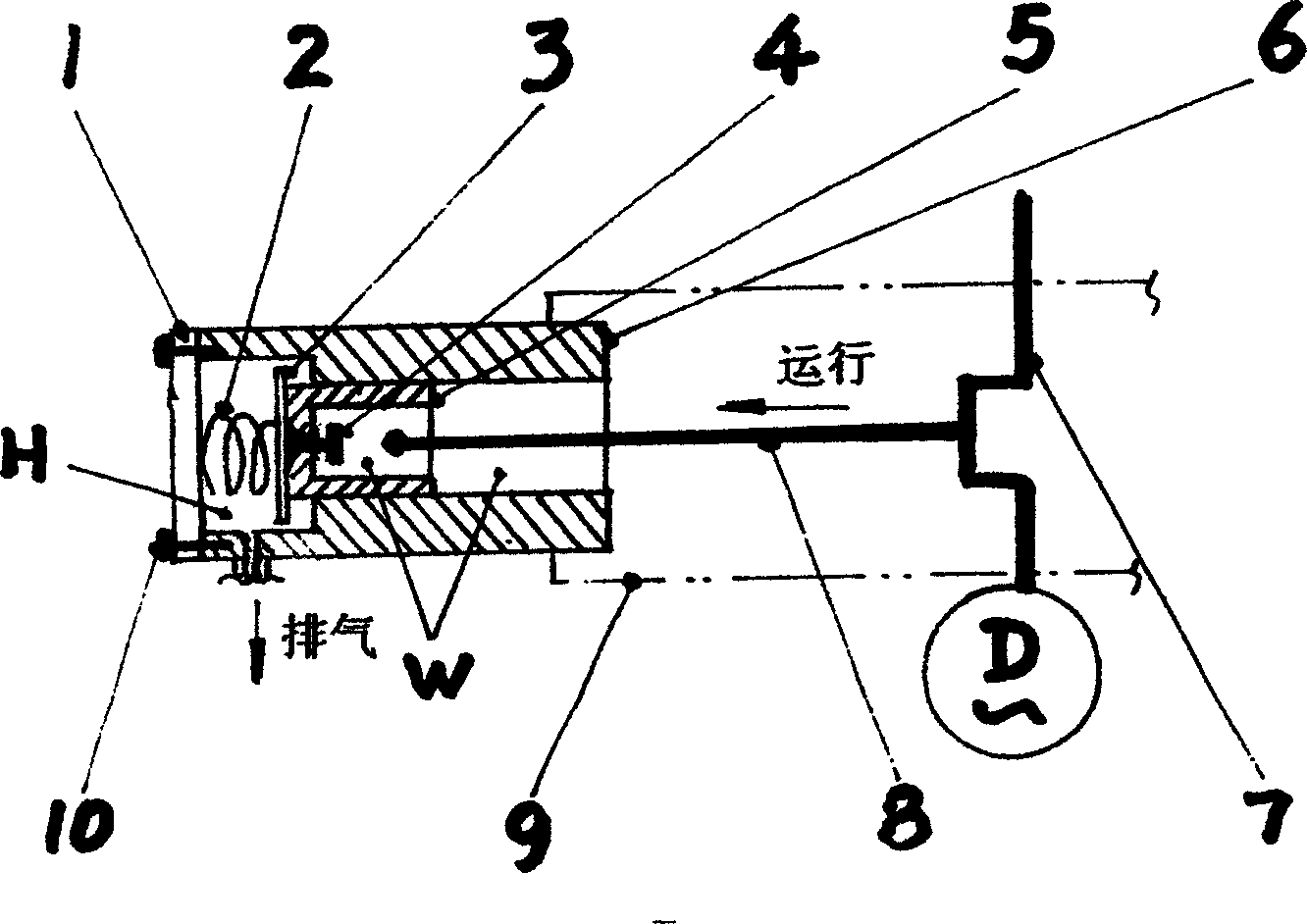
[0014] figure 1 An overview of the structure of the "no backlash" design of a crankshaft-driven compressor is highlighted.

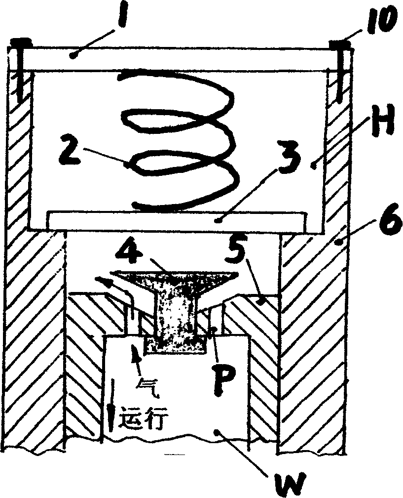
[0015] Depend on figure 2 As shown in the figure, the piston (5) which is doing the work of compressing and exhausting, after all the compressed high-pressure gas is squeezed into the high-pressure area (H), it continues to rush out of the cylinder against the exhaust valve plate (3). (6), and enter the high pressure area (H). At this time, the geometric space (“clearance”) between the piston (5), the conical suction valve block (4) and the exhaust valve plate (3), both theoretically and practically, is be able to make it "zero". The stroke of the piston (5) out of the cylinder (6) can usually be controlled at about one tenth of its effective suction stroke length.

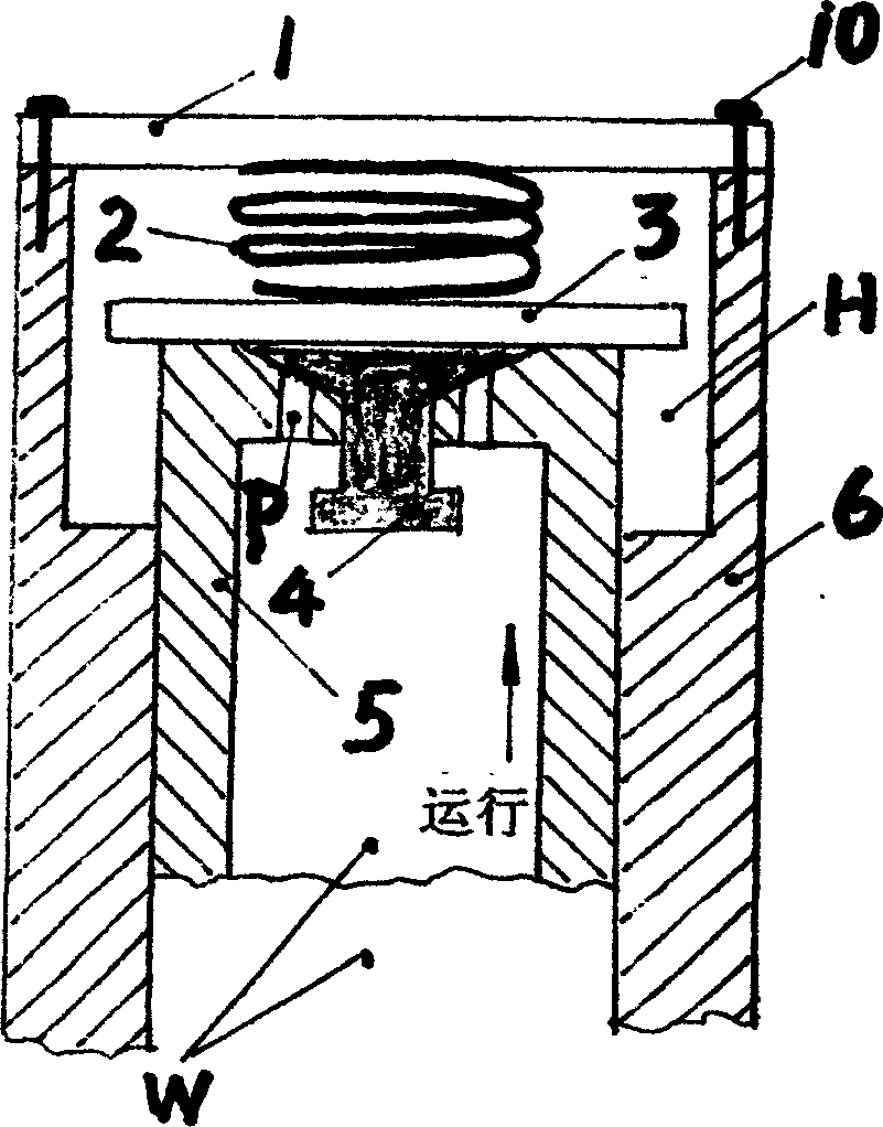
[0016] Depend on image 3 As shown, when the piston (5) is fully retracted into the cylinder (6), the exhaust valve plate (3) positioned by the spring (2) will naturally allow it to si...


PUM


Abstract

A 'non cross gap' design for a kind of piston double acting compressor. Piston rushes out of cylinder when piston exhausting against exhaust valve plate, and runs into high pressure zone, then a nonspace state--' non cross gap' is formed among piston, exhaust valve plate and intake block, thus improves the compression ratio or exhaust efficiency greatly.

Description

Technical field: [0001] The invention relates to a "clearance" structure design technology of a piston reciprocating compressor. Background technique: [0002] The vast majority of the compressors currently available are conventional piston compressors driven by the crankshaft, which have the advantages of simple manufacture, long service life and low material requirements, which cannot be compared with other types of compressors. Features, this is the main reason for its longevity since its inception; in addition, there are compressors that drive the reciprocating motion of the piston through linear electromagnetic vibration; and there are similar rumors of other types of piston reciprocating compressors. [0003] The shortcomings of the above varieties of compressors are: their working efficiency, that is, the working compression ratio or the exhaust efficiency, is always difficult to improve. One of the main reasons why it is difficult to improve their stagnation is that...

Claims


Application Information

Patent Timeline
IPC IPC(8): F04B35/04F04B53/12
Inventor 梁嘉麟
Owner 梁嘉麟
Why Eureka
Try Eureka