Fresnel lens spotlight

A Fresnel lens and spotlight technology, applied in the field of Fresnel lens spotlights, can solve problems such as complex design, and achieve the effects of increasing light quantity and high luminous efficiency

Inactive Publication Date: 2005-10-12
AUER LIGHTING
View PDF3 Cites 15 Cited by
  • Summary
  • Abstract
  • Description
  • Claims
  • Application Information

AI Technical Summary

Problems solved by technology

Moreover, the distance ratio between the lamp and the reflector and the distance ratio between the reflector and the Fresnel lens are set

Method used


Image

  • Fresnel lens spotlight
  • Fresnel lens spotlight
  • Fresnel lens spotlight

Examples


Embodiment Construction

[0042] In the following detailed description, the same reference numerals refer to the same parts or parts having the same function in different embodiments.

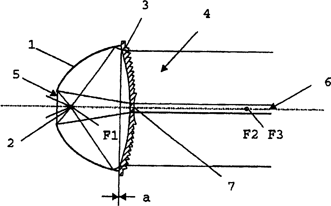
[0043] The following description refers to the appendix figure 1 , which shows an example of a Fresnel lens spotlight at the spot position. The Fresnel lens spotlight basically includes an elliptical reflector 1, a lamp 2 and a Fresnel lens 3, wherein the lamp 2 can be a halogen lamp or a discharge tube, and the Fresnel lens 3 is a lens with negative refractive power, preferably It is a biconcave Fresnel lens.

[0044] exist figure 1 The focal point F2 of the medium elliptical mirror 1 away from the mirror and the virtual or negative focal point F3 of the Fresnel lens 3 approximately coincide on the right-hand side.

[0045] The light 4 emitted by the spotlight is represented schematically in the figure by its outer edge beam.

[0046] The discharge arc of the filament or lamp 2 is placed substantially at the posi...


PUM


Abstract

In order to produce a Fresnel lens spotlight whose emitted light beam has an adjustable aperture angle, having a preferably ellipsoid reflector, a lamp and at least one Fresnel lens, which has a more compact form and is thus not only more space-saving but is also lighter than the conventional Fresnel lens spotlight, a lens with a negative focal length and a virtual focal point is used as the Fresnel lens.

Description

technical field [0001] The present invention relates to a Fresnel lens spotlight which emits a light beam with an adjustable aperture angle and includes a reflector, a lamp and at least one Fresnel lens. Background technique [0002] The illumination part of a conventional Fresnel lens spotlight generally consists of a lamp, a Fresnel lens and a spherical auxiliary reflector. Generally, the filament of the lamp is fixed at the center point of the spherical reflector. Therefore, part of the light emitted by the lamp is reflected back, helping the light in the front hemisphere to emit. Forward-directed rays are focused by a Fresnel lens. But how well the light is focused is determined by the distance between the Fresnel lens and the lamp. If the filament of the lamp is at the focal point of the Fresnel lens, the thinnest focused beam will be produced. This makes its optical path approximate to parallel lines, which is also called a spot. Reducing the distance between the ...

Claims


Application Information

Patent Timeline
IPC IPC(8): F21S2/00F21L4/00F21S8/00F21V5/00F21V5/04F21V7/00F21V9/08F21V14/06F21W131/20F21W131/406G02B3/08
CPCF21V9/08F21V14/06F21V5/045F21W2131/406F21L4/005F21V7/0008G02B3/08F21W2131/20
Inventor 卢迪格·吉特尔曼哈里·韦格纳
Owner AUER LIGHTING
Why Eureka
Try Eureka