Suction roll with sensors for detecting temperature and/or pressure

A sensor, sensing system technology, applied in the field of paper rolls, which can solve problems such as damaged fibers, unacceptable light transmission, moving fibers and sensor positions, etc.

Inactive Publication Date: 2005-10-12
STOWE WOODWARD
View PDF7 Cites 24 Cited by
  • Summary
  • Abstract
  • Description
  • Claims
  • Application Information

AI Technical Summary

Problems solved by technology

As such, drilling holes in the covering in the conventional manner will almost certainly damage the sensor, and possibly the fiber optic as well
In addition, during curing of the covering, the polymer material often shifts slightly on the core, and in turn may shift the position of the fibers and sensors; thus, it is not always possible to precisely determine the position of the fibers and sensors under the covering, shifting core may move the sensor or cable (or cables) to a position directly under the hole
Also, for proper performance, fiber optic cables typically have relatively high minimum bend radii; as such, attempts to weave optical fibers between the intended holes in the roll may result in unacceptable light transmission within the fibers

Method used


Image

  • Suction roll with sensors for detecting temperature and/or pressure
  • Suction roll with sensors for detecting temperature and/or pressure
  • Suction roll with sensors for detecting temperature and/or pressure

Examples


Embodiment Construction

[0024] The present invention is described more fully hereinafter, in which preferred embodiments of the invention are shown. However, this invention may be embodied in different forms and should not be construed as limited to the embodiments set forth herein. Rather, these embodiments are provided so that this disclosure will be thorough and complete, and will fully convey the scope of the invention to those skilled in the art. In the drawings, the same reference numerals refer to the same elements. Thicknesses and dimensions of some components may be exaggerated for clarity.

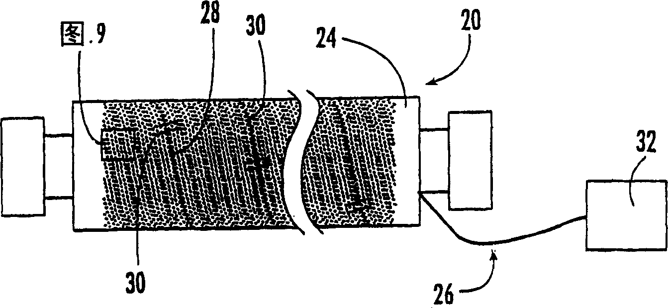
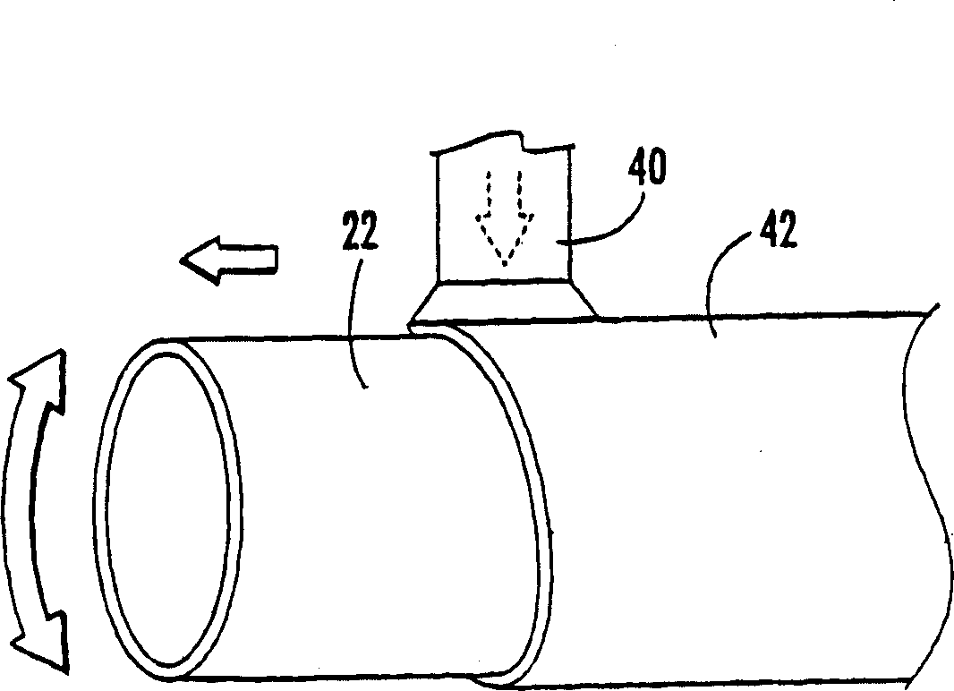
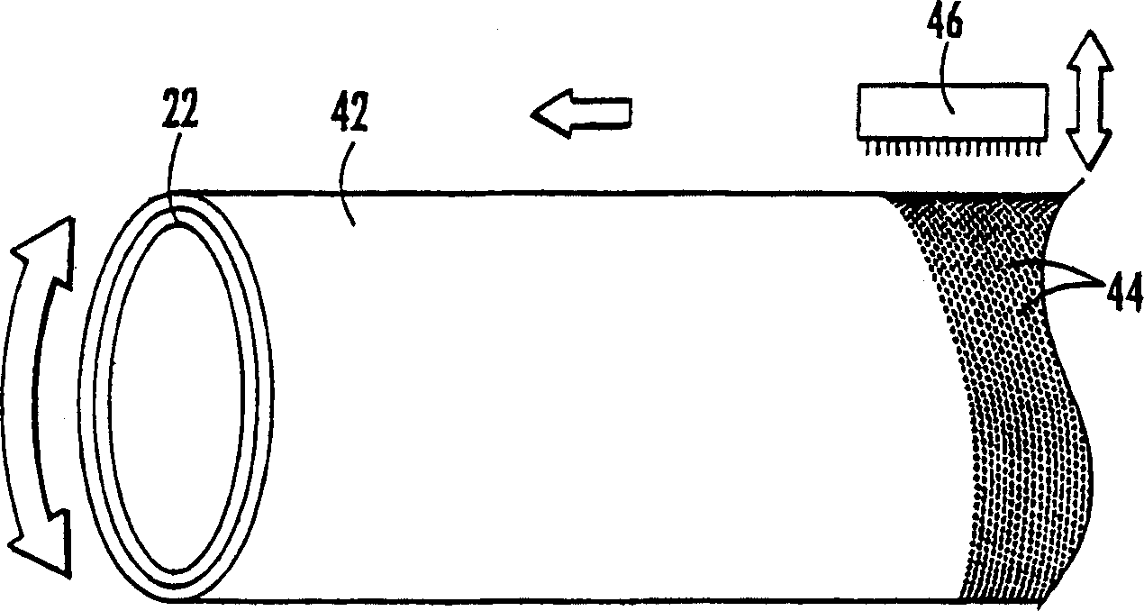
[0025] Referring now to the drawings, a suction roll, generally indicated by the reference numeral 20, is figure 1 displayed in . Suction roll 20 comprises a hollow cylindrical shell or core 22 (such as figure 2 visible) and a covering 24 (typically formed of one or more polymeric materials) surrounding the shell 22. A sensing system 26 for sensing pressure, temperature, or some other operating pa...


PUM


Abstract

a substantially cylindrical shell (22) having an outer surface and an internal lumen; a polymeric cover (24) circumferentially overlying the shell outer surface; and a sensing system (26). The sensing system includes: a plurality of sensors (30) embedded in the cover (24), the sensors (30) configured to sense an operating parameter of the roll (20); and a signal-carrying member (28) serially connected with and extending between the plurality of sensors (30). The signal-carrying member (28) follows a helical path over the outer surface of the shell (22), wherein the signal-carrying member (28) extends over more than one complete revolution of the shell outer surface (and, preferably, an intermediate segment of the signal-carrying member (28) extends over more than a full revolution of the roll (20) between adjacent sensors (30)).

Description

technical field [0001] This invention relates generally to industrial rolls, and more particularly to rolls used in the manufacture of paper. Background technique [0002] Cylindrical rolls are used in many industrial applications, especially those involving papermaking. Such rolls are often used in harsh environments where they are exposed to high dynamic loads and temperatures, as well as aggressive or corrosive chemical agents. As an example, in a typical paper machine, rolls are used not only to transport the fibrous web (or web panels) between processing stations, but also, in the case of press sections and calender rolls, to process the web itself into Paper. [0003] A paper machine may include one or more suction rolls arranged at various locations within the machine to extract moisture from the belt (such as a press felt) and / or the fibrous web. Each suction roll typically consists of a metal shell covered by a polymer covering with a plurality of holes extending...

Claims


Application Information

Patent Timeline
Patent Type & Authority Applications(China)
IPC IPC(8): G01L5/00D21F3/06D21F3/10F16C13/00G01K1/02G01K13/08G08C23/04
CPCD21F3/06D21F3/105
Inventor E·J·古斯塔夫松
Owner STOWE WOODWARD
Why Eureka
Try Eureka