Image quality compensation for duplex or triplex mode ultrasound systems

A technology of ultrasound and mode, applied in the field of ultrasound transmission, which can solve the problems of increasing the cost and complexity of ultrasound systems

Active Publication Date: 2005-10-19
SIEMENS MEDICAL SOLUTIONS USA INC
View PDF0 Cites 11 Cited by
  • Summary
  • Abstract
  • Description
  • Claims
  • Application Information

AI Technical Summary

Problems solved by technology

Nevertheless, multiple voltage supplies and switching between different voltage supplies add to the cost and complexity of the ultrasound system

Method used


Image

  • Image quality compensation for duplex or triplex mode ultrasound systems
  • Image quality compensation for duplex or triplex mode ultrasound systems
  • Image quality compensation for duplex or triplex mode ultrasound systems

Examples


Embodiment Construction

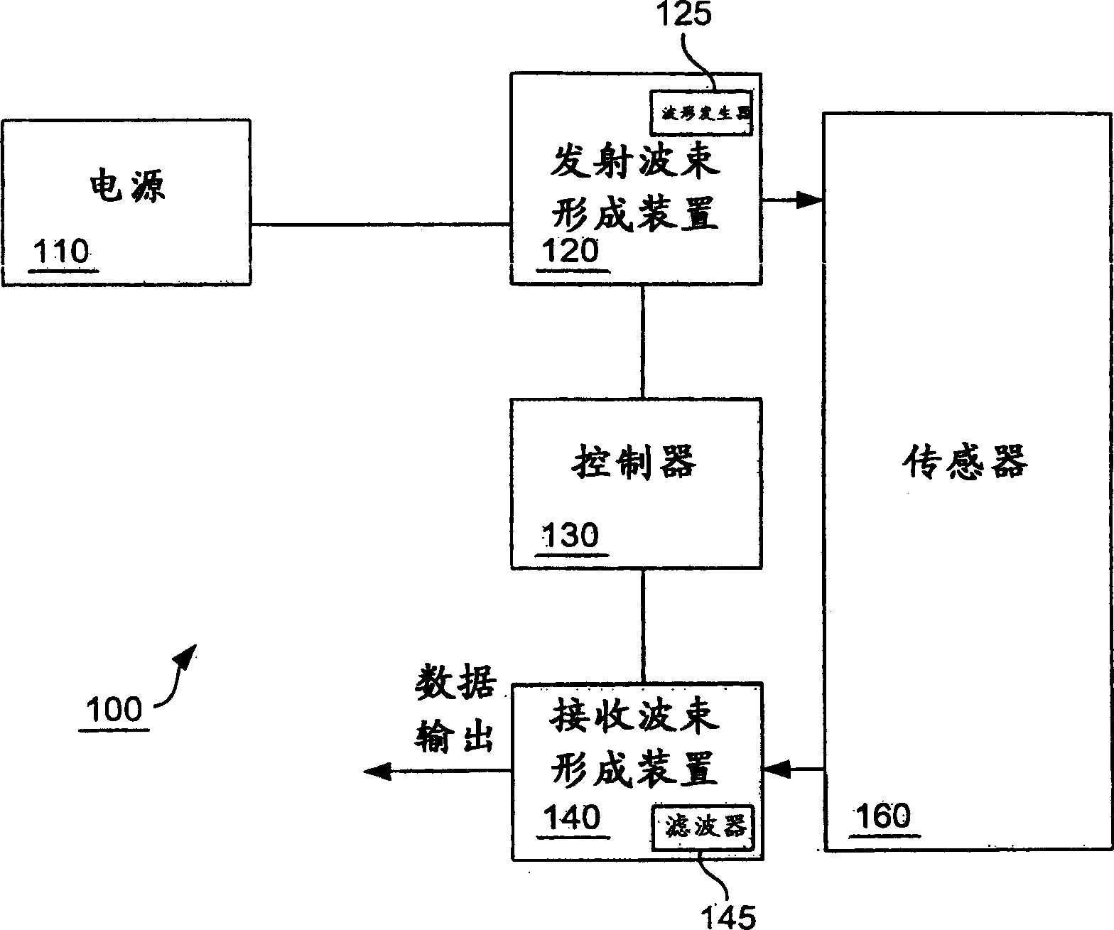
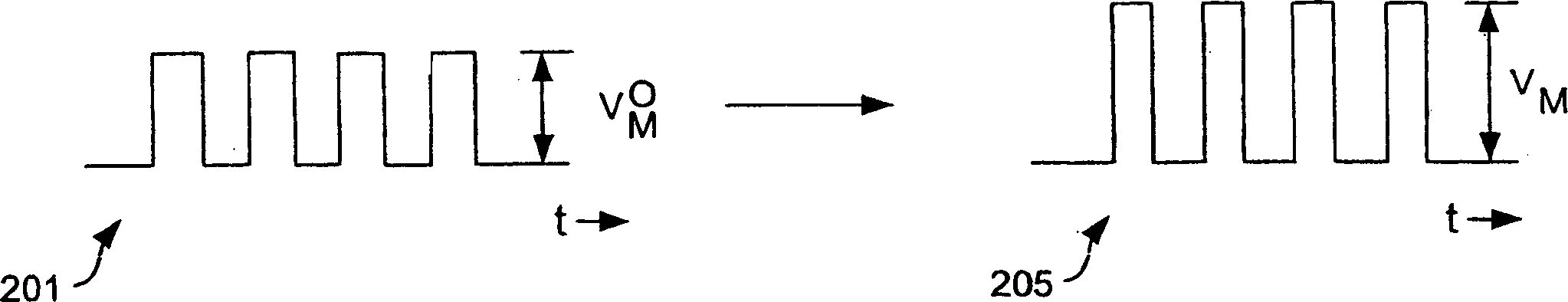
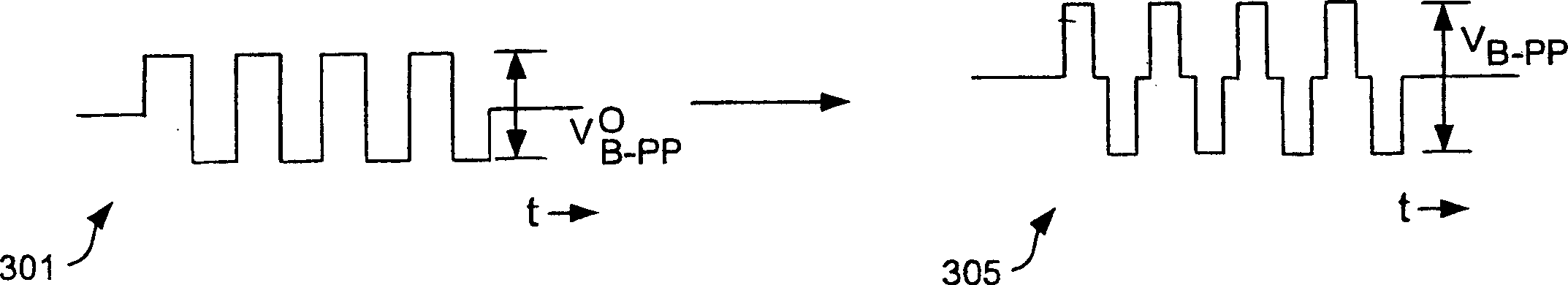
[0026] One of the challenges faced by designers of ultrasound imaging systems is the task of using a single fixed-voltage power supply in a multi-mode system. The dual-mode system effectively provides the user with the ability to view a single image interleaved from two images acquired by different operating systems. For example, a dual-mode system may present a combined image in which a B-mode image and a color-mode image are interleaved to provide enhanced information to the user. Likewise, a triple-mode system can provide a combined view based on B-mode, color-mode and spectral Doppler-mode. Since the various modes typically have different pulse shapes, operating the different modes at different peak power levels optimizes the performance of the system described above. These different peak power levels corresponding to the multiple modes of operation require diverse power supplies.

[0027] Each additional power supply and switching between power supplies adds cost and co...


PUM


Abstract

Duplex operation for ultrasound imaging uses a single fixed voltage level. Both B-mode and color-mode imaging are performed using a power level that may be less than the power level for single-mode B-mode imaging, and may be greater than the power level for single-mode color-mode imaging. A duty cycle of color-mode pulses may be reduced. To enhance image quality, the number of cycles in the B-mode pulse profile may be increased. To enhance image quality, the center frequency of the B-mode pulse profile may be reduced, and dynamic filtering for B-mode received pulses may be appropriately modified.

Description

technical field [0001] The present invention relates generally to ultrasound imaging, and more particularly to methods of ultrasound delivery that enable multiple imaging modalities. Background technique [0002] Usually, different imaging modes require different voltage levels to transmit appropriate instantaneous power levels, and different voltage levels require various voltage power supplies, which increases the complexity of the system. [0003] Ultrasound imaging systems produce a series of images depicting a part of the body. Ultrasound imaging has been widely used to observe tissue structures in the human body, such as the structure of the heart, organs in the abdomen, the fetus, and the vasculature. Typically, an ultrasound imaging system includes sensors for transmitting and receiving signals coupled to a beamforming device. The transmit beam forming device sends electrical pulses to the sensor within a predetermined time sequence to generate a transmit beam, whic...

Claims


Application Information

Patent Timeline
Patent Type & Authority Applications(China)
IPC IPC(8): A61B8/00A61B8/02A61B8/06A61B8/08A61B8/14G01S7/52G01S15/89
CPCA61B8/4416G01S15/8979A61B8/14A61B8/08A61B8/06A61B8/13A61B8/488G01S7/52074A61B8/00G01S7/52046G01S7/52025A61B8/56
Inventor J·R·克莱珀H·王
Owner SIEMENS MEDICAL SOLUTIONS USA INC
Why Eureka
Try Eureka