
Burner for stove and accessory

A technology of burners and stoves, which is applied in the direction of burners, gas fuel burners, combustion methods, etc., and can solve problems such as deterioration of combustibility, too narrow intervals, interference of flames, etc.

Inactive Publication Date: 2005-11-02
RINNAI CORP
View PDF1 Cites 9 Cited by
  • Summary
  • Abstract
  • Description
  • Claims
  • Application Information

AI Technical Summary

Problems solved by technology

[0003] However, the space between the radially formed notch-shaped flame holes becomes narrower on the radially inner side of the burner head.
Therefore, if the number of slit-shaped flame holes is too large, the space between the slit-shaped flame holes at the inner end in the radial direction will become too narrow, which will cause flame interference and damage caused by insufficient secondary air. Combustibility deterioration
As a result, the number of slit-shaped flame holes is limited, but there is a relatively large dead zone between the slit-shaped flame holes that expands radially outward.
As a result, thermal efficiency in the circumferential direction becomes poor

Method used


Image

  • Burner for stove and accessory
  • Burner for stove and accessory
  • Burner for stove and accessory

Examples


Embodiment Construction

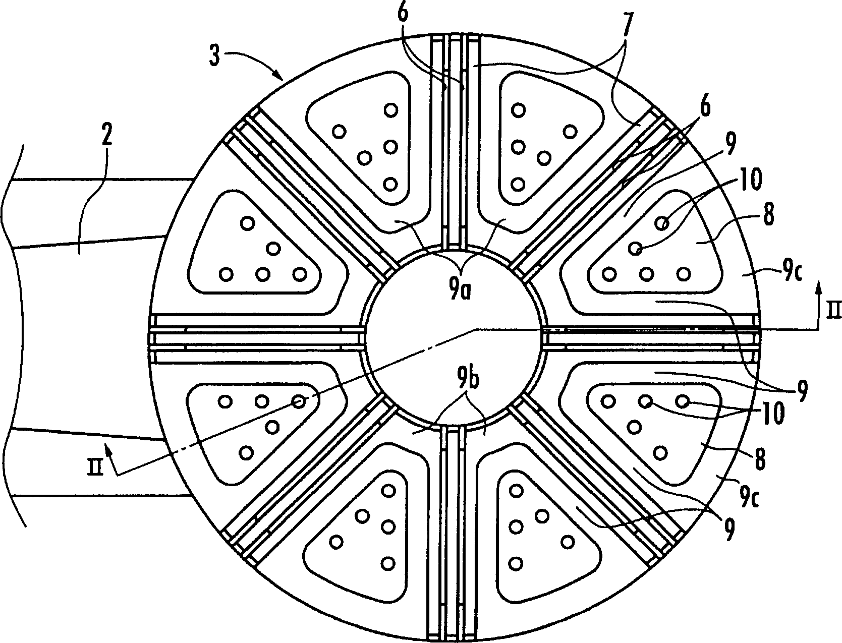
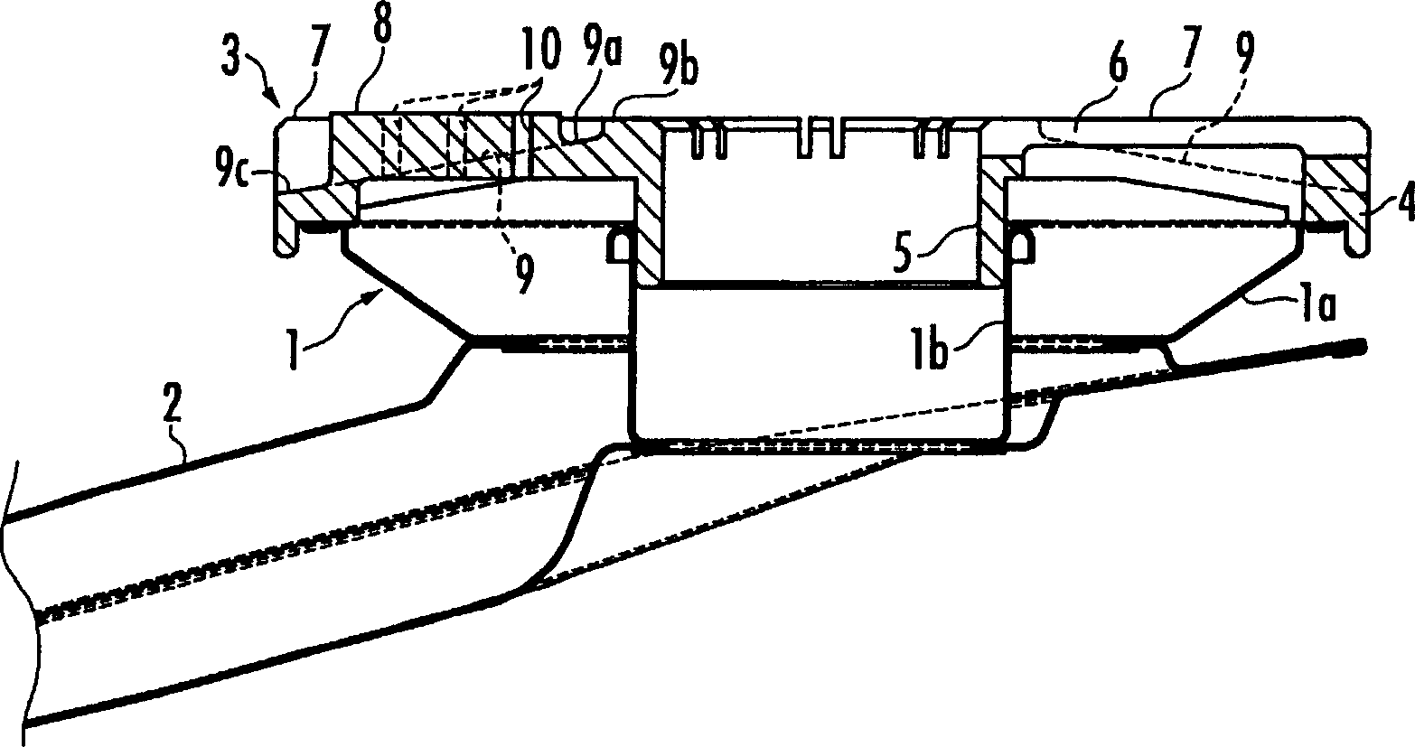
[0015] refer to figure 1 and figure 2 , 1 denotes a burner body of a burner for a stove, and the burner body 1 is formed in an upwardly open ring shape by a disk-shaped outer member 1a and a cylindrical inner member 1b. A mixture of gas and primary air is supplied to the burner body 1 via a mixing tube 2 connected to the burner body 1 . In addition, although the burner body 1 and the mixing tube 2 are made of thin metal plates, the burner body 1 and the mixing tube 2 may be integrally formed by casting.

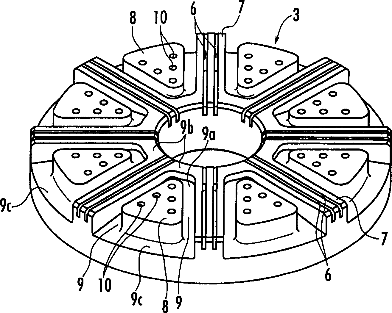
[0016] On the burner body 1 , an annular burner head 3 covering the burner body 1 from above is detachably mounted. The burner head 3 is a cast product, and has an outer peripheral seating portion 4 seated on the upper edge of the outer member 1a of the burner body 1, and a cylindrical portion embedded in the inner periphery of the inner member 1b of the burner body 1. 5. In addition, although not shown, a ring-shaped juice receiving pan with an inner diameter smaller th...


PUM


Abstract

A stove used combustor is formed with a plurality of incision-shaped flame holes (6) with radiation shape on the upper surface of the combustor head (3); the upper surface at the combustor head is formed with a groove (9) along the lateral margin of each radiation ray area (7) with the form that an approximate triangular platform part (8) remains, wherein the platform part is arranged at the part between each radioactive ray shaped area (7) and (7) which forms the incision-shaped flame holes (6), the radical exterior side of the combustor head is used as the hemline and the inner side of the radial direction is used as the top; and the platform part is formed with a plurality of circular hole shaped flame holes (10). The groove (9) is formed with the form of reaching the external circumstance of the combustor. The secondary air is supplied to the incision-shaped flame hole and the circular hole shaped flame hole from the outside of the combustor head and through the groove. Thereby the dead zone formed between each radioactive ray shaped area that forms the incision-shaped flame hole can be effectively utilized and the heat distribution in the circumference direction can be excellently arranged.

Description

technical field [0001] The invention relates to a burner for a stove which forms an upward flame. Background technique [0002] Conventionally, as a burner for a stove, a plurality of notch-shaped flame holes are radially formed on the upper surface of the burner head (see, for example, JP-A-2-146407). Here, on the burner for the stove, flame holes are usually arranged on the outer periphery of the burner head, but in this way, the flame contacts the part of the bottom surface of the cooking container that is close to the outside, resulting in low thermal efficiency. On the other hand, if on the upper surface of burner head, form the above-mentioned otch-shaped flame hole, the upward direction flame formed by the slit-shaped flame hole will contact the central part of the bottom surface of the cooking container, which improves the Thermal efficiency. In addition, flames are formed continuously in the radial direction of the burner head through the slit-shaped flame holes, ...

Claims


Application Information

Patent Timeline
Patent Type & Authority Applications(China)
IPC IPC(8): F23D14/06F23D14/58F24C3/08
Inventor 赤木万之富浦英行
Owner RINNAI CORP
Learn More