Rear plate for plasma display panel

A plasma and display panel technology, applied to AC plasma display panels, gas discharge electrodes, solid cathode parts, etc., can solve the problems of partition wall distortion, deformation, and difficulty in accurate electrode positioning

Inactive Publication Date: 2005-11-09
LG ELECTRONICS INC
View PDF2 Cites 6 Cited by
  • Summary
  • Abstract
  • Description
  • Claims
  • Application Information

AI Technical Summary

Problems solved by technology

As a result, during calcination, the partition walls may be distorted and deformed
Therefore, it is difficult to accurately position each electrode at the ideal position of each electrode, that is, the center position between the two partition walls

Method used


Image

  • Rear plate for plasma display panel
  • Rear plate for plasma display panel
  • Rear plate for plasma display panel

Examples


Embodiment Construction

[0014]Hereinafter, the rear panel of the plasma display panel of the preferred embodiment of the present invention will be described in detail with reference to the accompanying drawings.

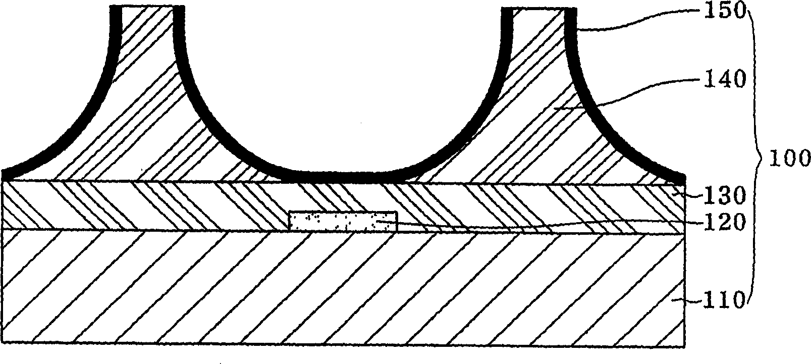
[0015] Such as figure 1 As shown, a rear panel 100 of a plasma display panel (hereinafter referred to as "PDP") according to the present invention includes a glass substrate 110, electrodes placed at predetermined intervals from each other and formed in a pattern on the upper surface of the glass substrate 110. 120, the insulating layer 130 formed on the upper surface of the electrode 120 and the upper surface of the glass substrate 110, the partition wall 140 formed on the upper surface of the insulating layer 130 and placed at a predetermined interval from each other, and the side surface and the bottom of the partition wall 140 A phosphor layer 150 is formed on the surface.

[0016] Hereinafter, a method of preparing the partition wall 140 of the present embodiment will be briefly descr...


PUM


Abstract

Disclosed is a rear plate of a plasma display panel. In the rear plate, barrier ribs are formed through etching after backing, and thus the completed barrier ribs are not deformed. Therefore, each electrode can be exactly located on a central portion between barrier ribs. When a PDP having front and rear plates attached to each other has been completed, optical characteristics of the PDP such as white brightness, color temperature, and contrast, and electric characteristics of the PDP such as voltage margin, power consumption, and electric efficiency, are improved, so that the reliability is improved.

Description

technical field [0001] The present invention relates to a rear panel for a plasma display panel. Background technique [0002] As generally known in the art, a plasma display panel (PDP) is a display device having a front glass substrate and a rear glass substrate with a discharge space formed therebetween so as to generate a plasma discharge in the discharge space, thereby causing phosphorescence in the discharge space The body is excited to emit light, thus displaying a fluorescent screen. [0003] The plasma display panel can be classified into a direct current plasma display panel (DC PDP) and an alternating current plasma display panel (AC PDP), among which the AC plasma display panel is the mainstream. US Patent No. 5,446,344 discloses a three-pole surface discharge AC plasma display panel, which is one of the representative AC plasma display panels. [0004] The plasma display panel includes a front panel and a rear panel assembled in parallel to each other. The fr...

Claims


Application Information

Patent Timeline
Patent Type & Authority Applications(China)
IPC IPC(8): H01J17/16H01J17/49
CPCH01J2211/225H01J11/36H01J11/12H01J2211/366H01J11/42H01J11/38H01J11/22
Inventor 赵原德
Owner LG ELECTRONICS INC
Why Eureka
Try Eureka