System for monitoring lamps at signal locations of railroad and adjustment method

A monitoring system and railway signal technology, which is applied in the direction of railway signal and safety, can solve the problems of anti-interference threshold voltage limit, etc., and achieve the effect of improving anti-interference ability, reducing cost and improving energy saving performance

Inactive Publication Date: 2005-11-16
王世午
View PDF0 Cites 6 Cited by
  • Summary
  • Abstract
  • Description
  • Claims
  • Application Information

AI Technical Summary

Problems solved by technology

This method has the advantages of saving energy and increasing the control distance of the signal machine, but the disadvantages are: ①It is necessary to change the system power supply from 220V to 110V, which is not suitable for the existing power supply system; ②As long as the LED light source has microampere current It can make it glow, so it is necessary to set a threshold circuit in the LED light source to ensure that the LED light source does not emit light when the interference power is below a certain value.
When the power supply is 110V, the anti-interference threshold voltage is limited by the power supply voltage. In some strong interference occasions, if the interference voltage exceeds 80V, it cannot be used
③ Still not suitable for the existing JZXC-16F filament supervisory relay

Method used


Image

  • System for monitoring lamps at signal locations of railroad and adjustment method
  • System for monitoring lamps at signal locations of railroad and adjustment method
  • System for monitoring lamps at signal locations of railroad and adjustment method

Examples


Embodiment Construction

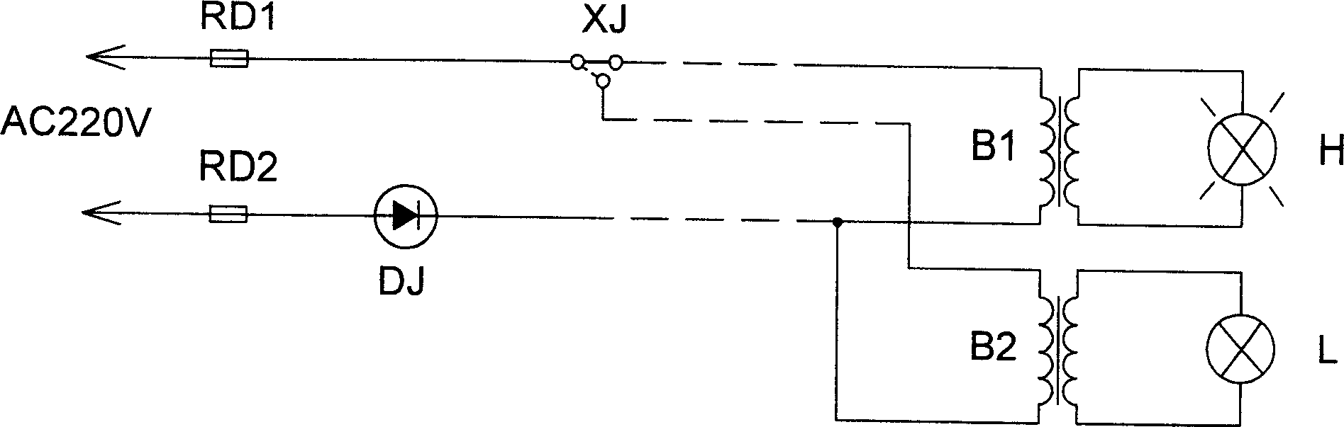
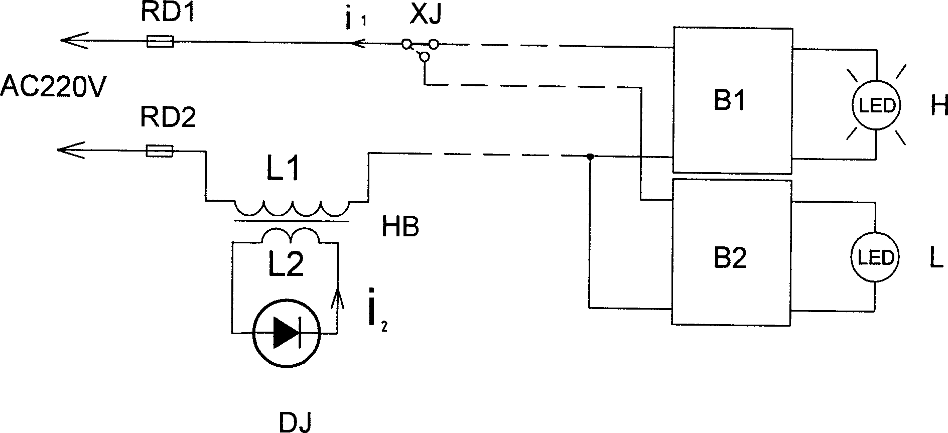
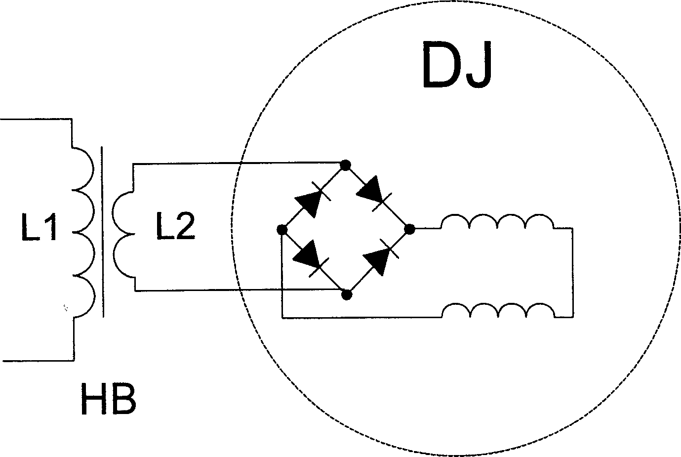
[0029] Such as figure 2 As shown, the present invention includes a signal relay XJ, a filament supervision relay DJ, a lighting unit B, signal lamps H, L and a mutual inductance transformer HB, the filament supervision relay DJ is JZXC-H18 type, and the two signal lamps H and L are originally Do not connect the two lighting units B H , B L output terminals of the two lighting unit B H , B L The input terminals of each lighting unit are respectively connected in parallel to the power supply terminal, and one input terminal of each lighting unit is respectively connected to the two contact terminals of the signal relay XJ, and the common terminal of the signal relay XJ is connected to an overcurrent protection After the device RD1 is connected to the power supply terminal, each lighting unit B H , B L The other input terminals of the mutual induction transformer are respectively connected, and connected in series with the primary of the mutual induction transformer HB and ...


PUM


Abstract

A signal lamp monitor system for railway and its regulating method are disclosed. The mutual induction transformer is used to connect the filament monitoring relay in the loop and the number of turns and the voltage ratio of said mutual induction transformer are regulated according to the working current in filament monitoring relay and loop, so monitoring the working current in circuit and in turn the failure in the circuit without change in the voltage of system power supply.

Description

technical field [0001] The invention relates to a railway signal lighting monitoring system and an adjustment method thereof. technical background [0002] The existing railway signal lighting monitoring system such as figure 1 As shown in , the signal lamps H and L are respectively connected to the output terminals of the two lighting units B, the input terminals of the two lighting units B are respectively connected in parallel to the power supply terminals, and are connected in series between one input terminal of the lighting units and the power supply There is a contact of the signal relay XJ. The power supply supplies power to the signal lamp after being stepped down by the lighting unit. The lighting unit and the control circuit form a lighting circuit. The current input to the lighting unit is the working current of the lighting circuit. For safety reasons, the filament supervision relay DJ is connected in series between the other input terminal of the lighting unit...

Claims


Application Information

Patent Timeline
Patent Type & Authority Applications(China)
IPC IPC(8): B61L23/00
Inventor 王世午
Owner 王世午
Why Eureka
Try Eureka