Power module for ac/ac power conversion

A power conversion and power technology, applied in the field of power modules, can solve problems such as inability to apply three-phase-three-phase conversion

Inactive Publication Date: 2005-11-16
DAIKIN IND LTD
View PDF0 Cites 7 Cited by
  • Summary
  • Abstract
  • Description
  • Claims
  • Application Information

AI Technical Summary

Problems solved by technology

[0010] 4) "A/F IPM" technology is not suitable for three-p...

Method used


Image

  • Power module for ac/ac power conversion
  • Power module for ac/ac power conversion
  • Power module for ac/ac power conversion

Examples


Embodiment Construction

[0122] A power module for AC / AC power conversion according to an embodiment of the present invention will be described in detail below with reference to the accompanying drawings.

[0123] The present invention includes three types of power modules for AC / AC power conversion:

[0124] (A) The first type of power module is based on a boost topology.

[0125] (B) The second type of power module is based on a boosted three-level topology.

[0126] (C) The third type of power module is based on buck / boost current source topology.

[0127] Each of the proposed three power modules can be applied to different situations by adding / removing corresponding necessary / unnecessary individual devices.

[0128] (A) The first type:

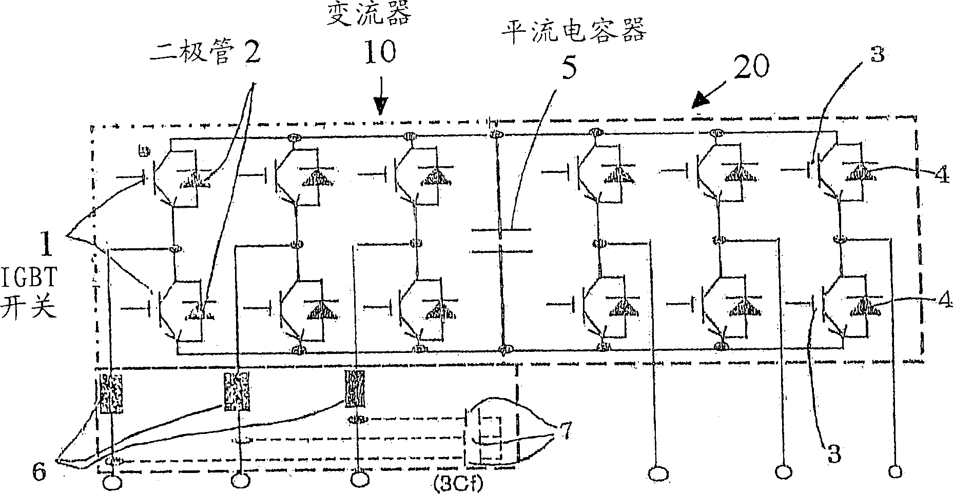
[0129] image 3 A basic power conversion module is shown for converting a constant voltage and constant frequency three-phase AC power supply to a three-phase AC output power supply with a variable voltage and variable frequency control system. The basic powe...


PUM


Abstract

An arrangement is provided a converter, an inverter, a smoothing condenser connected between the converter and the inverter, and reactors each connected between the connection point of each pair of IGBT switches of the converter and the output terminal of each phase of the AC power source. The converter has three pairs of IGBT switches for three phases that are serially connected to one another and connected in parallel to one another. First diodes are each connected in reversed polarity and in parallel to each IGBT switch. The inverter has three pairs of IGBT switches that are serially connected to one another and connected in parallel to one another. Each diode is connected in reversed polarity and in parallel to each IGBT switch.

Description

technical field [0001] The present invention relates to power modules for AC / AC power conversion. More specifically, the present invention relates to a power module for converting an AC voltage to a desired AC voltage using a converter and an inverter. Background technique [0002] For many years, a power module with two switches or a power module with four switches is a device that has been widely used only in the field of power conversion. The main reason for standardizing these power modules is for simplicity and commonality. This type of power module is commercially available under various names such as: Integrated Gate Bipolar Transistor Module "IGBT MOD", Application-Specific Intelligent Module "ASIPM", and Dual In-line Package Intelligent Power Module "DIP- IPM". All of the above examples were developed only to improve the state of the load side application. However, the grid side of transmission equipment has been neglected for lack of reason to compete vigorousl...

Claims


Application Information

Patent Timeline
IPC IPC(8): H02M1/08
Inventor 阿卜杜拉・梅基
Owner DAIKIN IND LTD
Why Eureka
Try Eureka