Motor matrix cascade control circuit

A cascade control and power supply circuit technology, applied in the direction of motor generator control, AC motor control, control system, etc., can solve the problems of no isolation protection, waste of resources, high cost, etc., to improve circuit safety, realize voltage reduction and Noise reduction, increased stability effects

Active Publication Date: 2022-03-25
深圳奕航智能有限公司
View PDF6 Cites 0 Cited by
  • Summary
  • Abstract
  • Description
  • Claims
  • Application Information

AI Technical Summary

Problems solved by technology

[0004]1. The stepper motor is connected with an external driver and a microcontroller, but the controller circuit has high cost, complex and cumbersome installation and wiring, no isolation protection, and circuit safety It is low in size, large in size, cannot be used in scenes with relatively limited motor security space, and cannot achieve closed-loop control of the target position without an external absolute position sensor
[0005]2. Integrated stepper motor, that is, a stepper motor with integrated driver, absolute value position sensor and bus controller, but since the motor is a microcontroller corresponding Control a stepper motor, so there are application scenarios that cannot be applied to large-scale motors, resulting in a waste of resources

Method used


Image

  • Motor matrix cascade control circuit
  • Motor matrix cascade control circuit
  • Motor matrix cascade control circuit

Examples


Embodiment

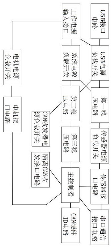
[0034] Such as Figure 1-Figure 5 As shown, this embodiment provides a motor matrix cascaded control circuit, including a power supply circuit and a controller circuit, and the power supply circuit is connected to the controller circuit;

[0035] The power circuit includes a working power input interface, a system power load switch, a motor power load switch, a sensor power load switch, a CAN transceiver power load switch, a first voltage stabilizing circuit, a second voltage stabilizing circuit and a third voltage stabilizing circuit; The working power input interface is respectively connected to the first end of the system power load switch and the first end of the motor power load switch, and the second end of the system power load switch is respectively connected to the first voltage stabilizing circuit The first end of the first voltage stabilizing circuit is connected to the first end of the second voltage stabilizing circuit, the second end of the first voltage stabiliz...

Embodiment approach

[0058] In a specific implementation, the isolated CAN transceiver interface circuit includes two CAN interface circuits, one of which is a backup circuit for connecting more slave controllers, and each CAN interface circuit includes a dual-way PNP transistor. For driving the CAN signal LED indicator light, wherein, the first collector C1 of the dual-path PNP transistor is connected to the eighth resistor R307 and the second light-emitting diode D305 in turn, and then connected to the system ground SGND, and the first collector of the dual-path PNP transistor is connected to the system ground SGND. A base B1 is connected to the eighth resistor R305 and connected to the CAN1_TX pin of the main controller, and the first emitter E1 of the dual PNP transistor is connected to the 3.3VCAN pin of the main controller. The second collector C2 of the dual PNP transistor is connected to the ninth resistor R304 and the third light-emitting diode in turn, and then connected to the system gro...


PUM


Abstract

The invention discloses a motor matrix cascade control circuit, which comprises a power supply circuit and a controller circuit, and is characterized in that the power supply circuit is connected with the controller circuit; the power supply circuit comprises a working power supply input interface, a system power supply load switch, a motor power supply load switch, a sensor power supply load switch, a CAN transceiver power supply load switch, a first voltage stabilizing circuit, a second voltage stabilizing circuit and a third voltage stabilizing circuit. The controller circuit comprises a main controller, a sensor interface circuit, an isolation CAN transmit-receive interface circuit and a motor interface circuit. According to the invention, the highly integrated motor matrix cascade control circuit is arranged, so that the flexibility of the controller circuit capable of being matched with peripheral equipment is high, and power supply load switches are allocated to each power supply, so that the circuit is isolated, and the working stability of the system is improved.

Description

technical field [0001] The invention belongs to the technical field of motor control, and in particular relates to a motor matrix cascade control circuit. Background technique [0002] The motor matrix is ​​an arrayed motion control system that includes hundreds or even thousands of motor units. Through the linear motion unit, the rotational motion of the motor is converted into lifting and stretching in the three-dimensional space. Under the control of the computer, it can present curves, Various shapes such as curved surface, plane, text and three-dimensional patterns to meet the needs of various application scenarios. For example: the art installations of medium and large event venues use each motion unit as a pixel, and then a large number of pixels form a giant screen, and through regular coordinated movement, it shows an artistic pattern. [0003] In the prior art, the control method for the motor matrix mainly includes: [0004] 1. The stepper motor is connected wit...

Claims


Application Information

Patent Timeline
Patent Type & Authority Applications(China)
IPC IPC(8): H02P8/40H02P25/16
CPCH02P8/40H02P25/16
Inventor 李楷汤晨雨秦梓航
Owner 深圳奕航智能有限公司
Why Eureka
Try Eureka