
Throttle valve device and air conditioner

A throttle valve and valve chamber technology, which is applied in valve devices, valve operation/release devices, and valve devices for absorbing fluid energy, etc. Propagation of moving sound, noise reduction effect

Active Publication Date: 2005-11-23
SAGINOMIYA SEISAKUSHO INC
View PDF6 Cites 10 Cited by
  • Summary
  • Abstract
  • Description
  • Claims
  • Application Information

AI Technical Summary

Problems solved by technology

Therefore, a vibration-type pressure change occurs, which excites the vibration of the piping, etc., and generates noise.
In this regard, in the throttle valve device of the prior art, no fundamental countermeasures have been taken to reduce the vibration itself generated by the throttling part in the throttle valve device, and the reduction of noise is limited.

Method used


Image

  • Throttle valve device and air conditioner
  • Throttle valve device and air conditioner
  • Throttle valve device and air conditioner

Examples


Embodiment Construction

[0027] Embodiments of the present invention will be described in detail below with reference to the accompanying drawings.

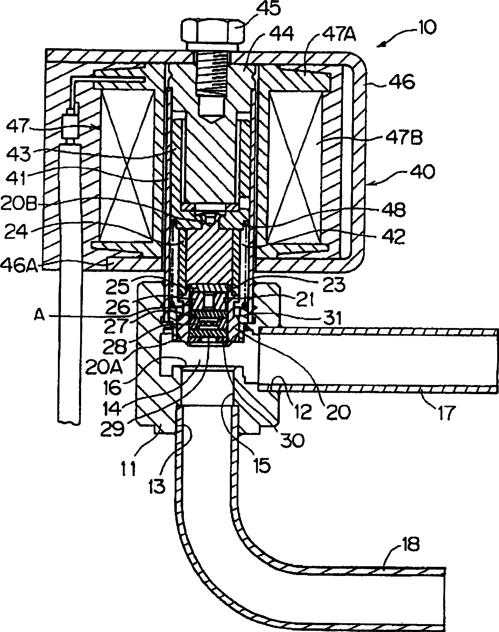
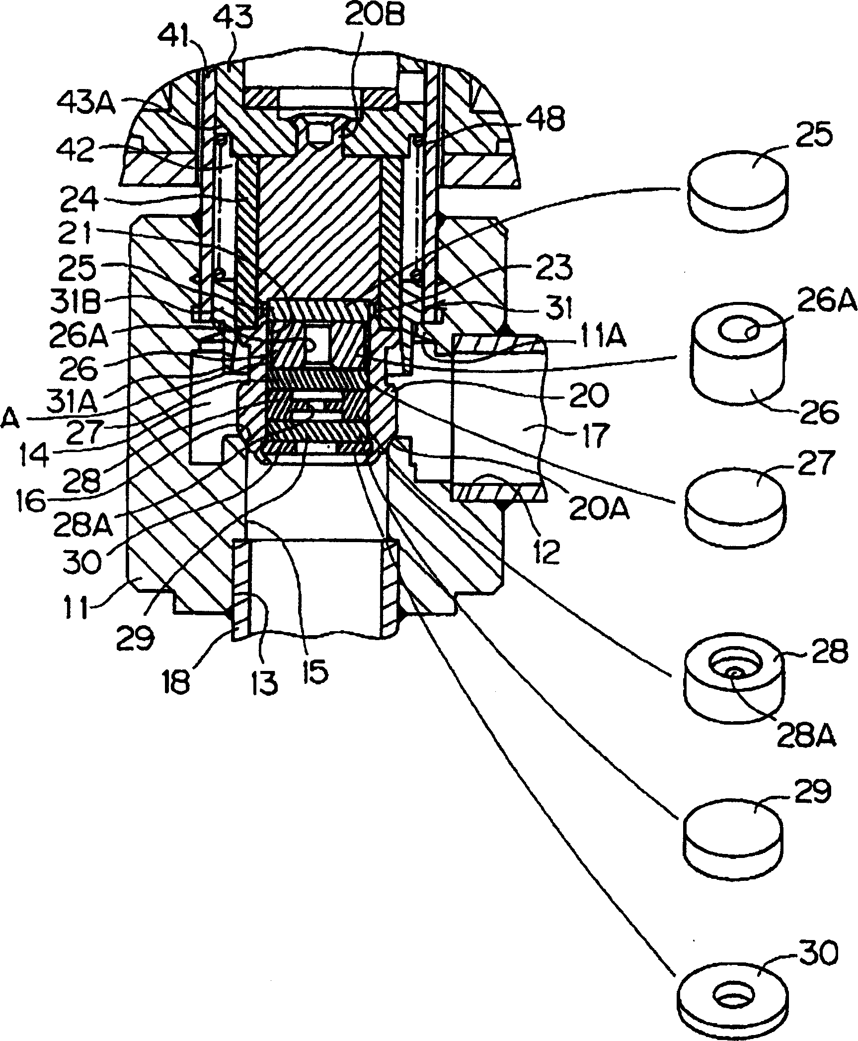
[0028] Such as figure 1 As shown, the throttle valve arrangement 10 has a valve sleeve 11 . The valve sleeve 11 defines a first inlet and outlet 12 , a second inlet and outlet 13 , a valve chamber 14 directly connected to the first inlet and outlet 12 at ordinary times, and a valve port 15 arranged between the valve chamber 14 and the second inlet and outlet 13 . A valve seat portion 16 is defined around an opening end of the valve port 15 on the valve chamber 14 side. Connecting pipes 17 and 18 are respectively connected to the first inlet and outlet 12 and the second inlet and outlet 13 .

[0029] The valve body 20 is provided in the valve chamber 14 so as to be movable in the vertical direction (valve lift direction) in the drawing. The valve body 20 is movable between a closed position of the valve and an open position of the valve, wherein, in t...


PUM


Abstract

The purpose of this invention is to effectively reduce noise, by reducing vibration itself generated in a throttle part in a throttle valve device. A shock absorbing member 26 and a throttle member 28 are arranged in series when viewing a fluid flow flowing in a passage, in the passage for communicating and connecting a first inlet-outlet port 12 with a second inlet-outlet port 13 in a state of closing a valve element 20.

Description

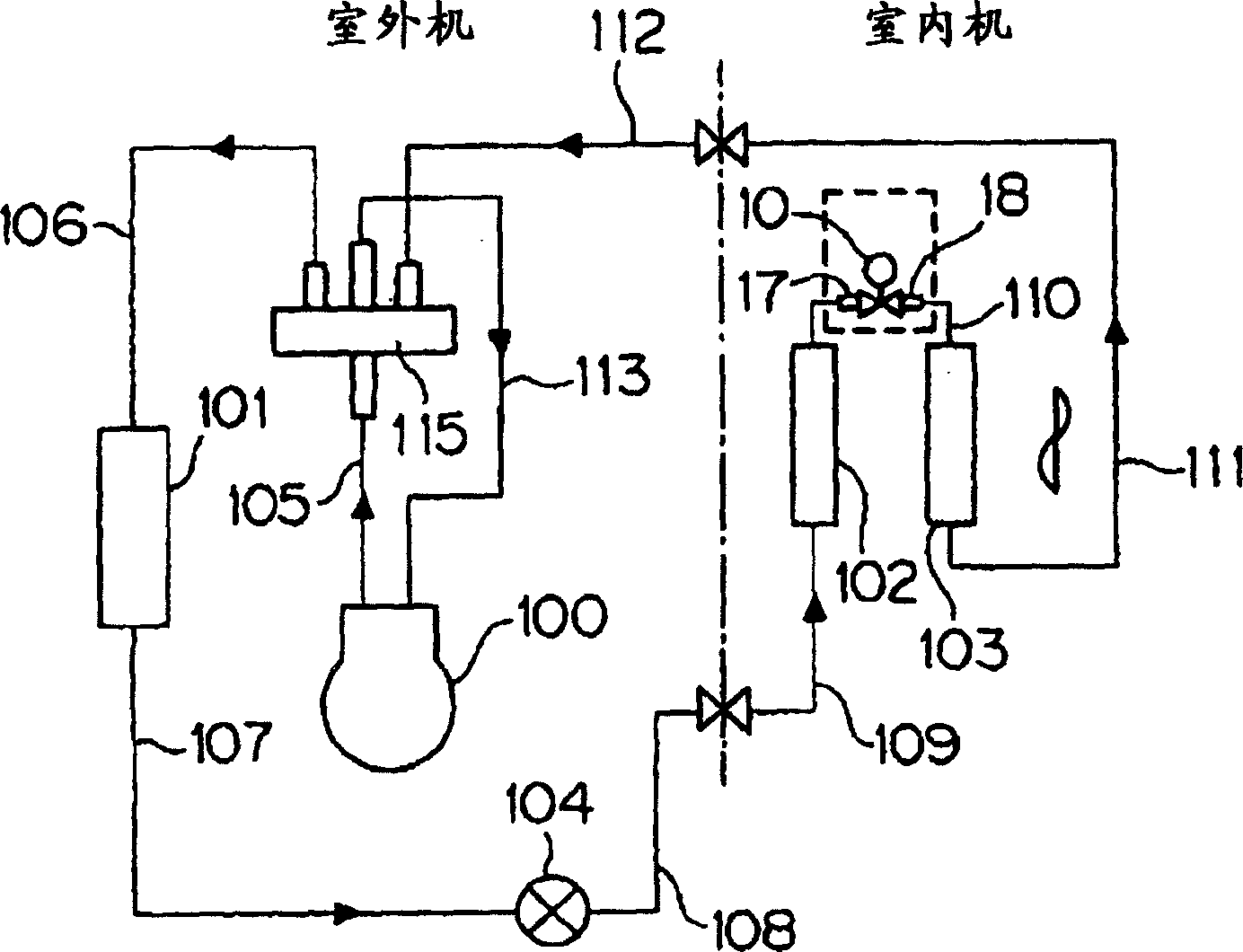
technical field [0001] The present invention relates to a throttle valve device and an air conditioner, and particularly relates to a throttle valve device and an air conditioner used as a valve for dehumidification in an air conditioner having a dehumidification mode. Background technique [0002] As an air conditioner that performs a dehumidification operation, an air conditioner with a dehumidification mode is known in which the indoor heat exchanger is divided into two, and between the two indoor heat exchangers A throttle valve device (throttle valve for dehumidification, circulating drying valve) is installed between the throttle valves in the closed state. During the dehumidification operation, the refrigerant flows through and closes the valve to function as a throttle valve. The throttling path of the throttling valve device uses the indoor heat exchanger on the upstream side as the condenser and the indoor heat exchanger on the downstream side as the evaporator amo...

Claims


Application Information

Patent Timeline
Patent Type & Authority Applications(China)
IPC IPC(8): F16K47/02F16K1/00F16K31/06F25B29/00F25B41/06
Inventor 杉田三男菅野治入子隆之芦泽久幸丸山美穗
Owner SAGINOMIYA SEISAKUSHO INC
Learn More