Adaptive valley point noise reduction method and system

A noise reduction system, self-adaptive technology, applied in speech analysis, instruments, etc., to achieve the effect of noise suppression

Inactive Publication Date: 2005-11-23
INST OF ACOUSTICS CHINESE ACAD OF SCI +1
View PDF0 Cites 11 Cited by
  • Summary
  • Abstract
  • Description
  • Claims
  • Application Information

AI Technical Summary

Problems solved by technology

But in some applications, such as hearing aids, mobile phones, PDAs, conference room microphones, etc., the environment they are used in is usually ever-changing, and the noise sources are very complex. They may be in different directions and distributed in different frequency bands, for example, in conference rooms , the

Method used


Image

  • Adaptive valley point noise reduction method and system
  • Adaptive valley point noise reduction method and system
  • Adaptive valley point noise reduction method and system

Examples


Embodiment Construction

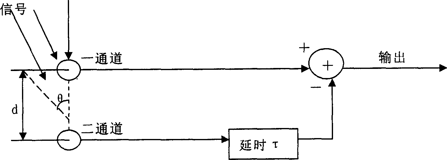
[0031] Figure 4 It is a functional block diagram of an adaptive valley point noise reduction system according to an embodiment of the present invention. As shown in the figure, two non-directional microphones (not shown in the figure) receive the acoustic signal, and after sampling and analog-to-digital conversion, the sampled signal f( n) and b(n) are output to the first channel and the second channel respectively, and f(n) and b(n) are respectively delayed by delayer 11 τ=d / cf s After (f s is the sampling frequency), and b(n), f(n) signals are subtracted on the first and second adders 12 to obtain forward and backward directivity signals x(n) and y(n), and then Signals x(n) and y(n) are respectively sent to the analysis filter bank 13 for frequency division to obtain a plurality of forward subband signals and backward subband signals x(n, f) and y(n, f), Each back sub-band signal y (n, f) is sent into the adaptive filter 14 of this frequency band respectively again, W i ...


PUM


Abstract

The invention discloses a system and method of sub strip impulse dip point noise reduction. It uses first access sampling signal and second access sampling signal which are outputted by two non-directing microphones separately minus second access sampling signal and first access sampling signal which have been time-delayed to obtain forward directing signal and rear directing signal; it then decomposes it into many fore-and-after sub strip signals; impulse filter does multiplication with the corresponding strip rear sub strip signal and impulse filter factor and outputs the adjust signal of rear sub strip; accumulator uses each strip's foreword sub strip signal minus rear sub strip adjust signal and outputs it; at last synthesis filter set accumulates the outputs of accumulator and outputs the signals. The dip spots of different strip can align several noise sources at the same time to assure controlling the noise of output signals.

Description

technical field [0001] The invention relates to a voice noise reduction method, more specifically, the invention relates to an adaptive directivity voice noise reduction method. Background technique [0002] A directional hearing device (or instrument) usually utilizes the characteristic that the target signal source and the noise signal source come from different directions to achieve the enhancement of the target signal and the suppression of the noise signal. At present, this directional acoustic signal pickup device has two modes: one has fixed directivity, including a single directional microphone and a double microphone pair (dipole), etc. The so-called fixed directivity refers to enhancing and The attenuation cannot change with the azimuth of the target sound source and the noise source; the other kind of directivity is adaptive, and the system parameters can be adjusted according to the change of the azimuth of the target sound source and the noise source to dynamica...

Claims


Application Information

Patent Timeline
IPC IPC(8): G10L21/0232
Inventor 程晓斌李晓东刘建颜永红
Owner INST OF ACOUSTICS CHINESE ACAD OF SCI
Why Eureka
Try Eureka