
Color cathode ray tube apparatus

A cathode ray tube and color technology, applied in the direction of cathode ray tube/electron beam tube, electrode device and related components, screen tube, etc., to achieve the effect of excellent focusing characteristics

Inactive Publication Date: 2005-11-23
MATSUSHITA TOSHIBA PICTURE DIS
View PDF1 Cites 2 Cited by
  • Summary
  • Abstract
  • Description
  • Claims
  • Application Information

AI Technical Summary

Problems solved by technology

However, even with the conventional techniques described above, it is difficult to simultaneously reduce the spot diameter in the horizontal direction and the spot diameter in the vertical direction

Method used


Image

  • Color cathode ray tube apparatus
  • Color cathode ray tube apparatus
  • Color cathode ray tube apparatus

Examples


Embodiment 1

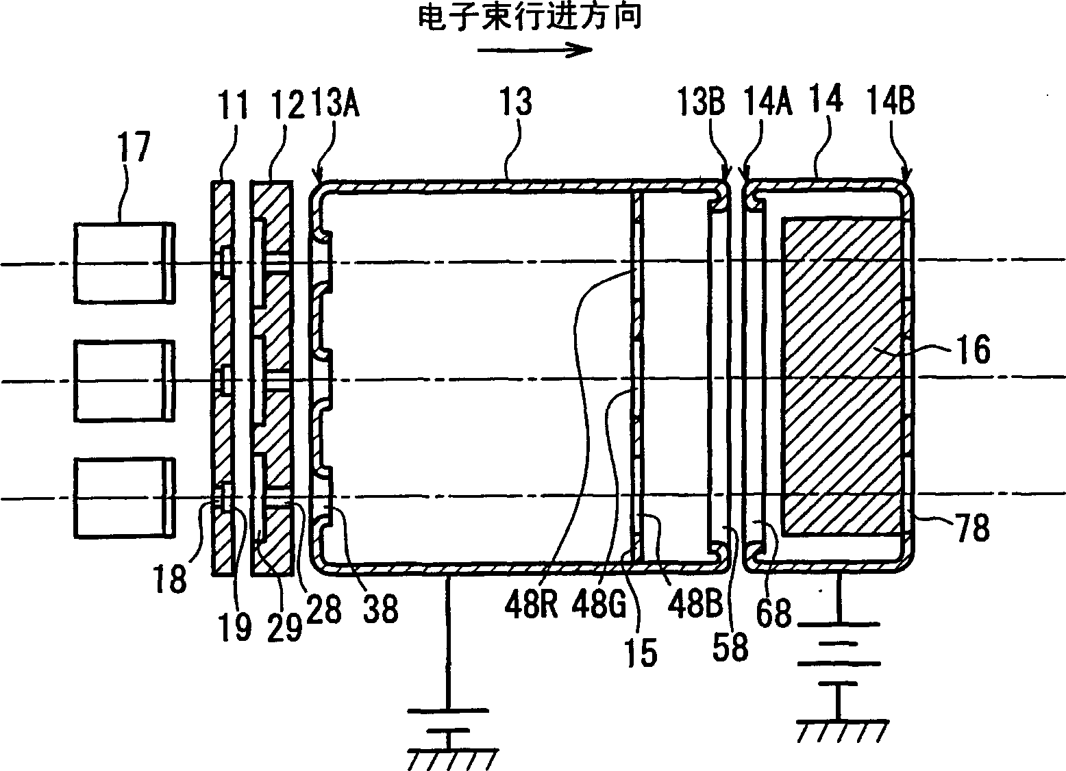
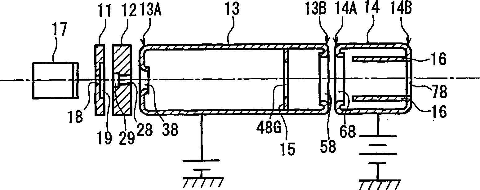
[0053] The color cathode ray tube device in Embodiment 1 will be described below with reference to FIGS. 1-6, which includes an electron gun having a second field correction electrode arranged parallel to the horizontal It consists of a pair of sheet-shaped electrodes on the plane of the traveling direction, and has a structure in which three beams of electron beams pass between the pair of sheet-shaped electrodes. It should be noted that, except for the structure of the electron gun, the color cathode ray tube device of this embodiment has the same structure as a conventional color cathode ray tube device, and a description thereof is omitted here.

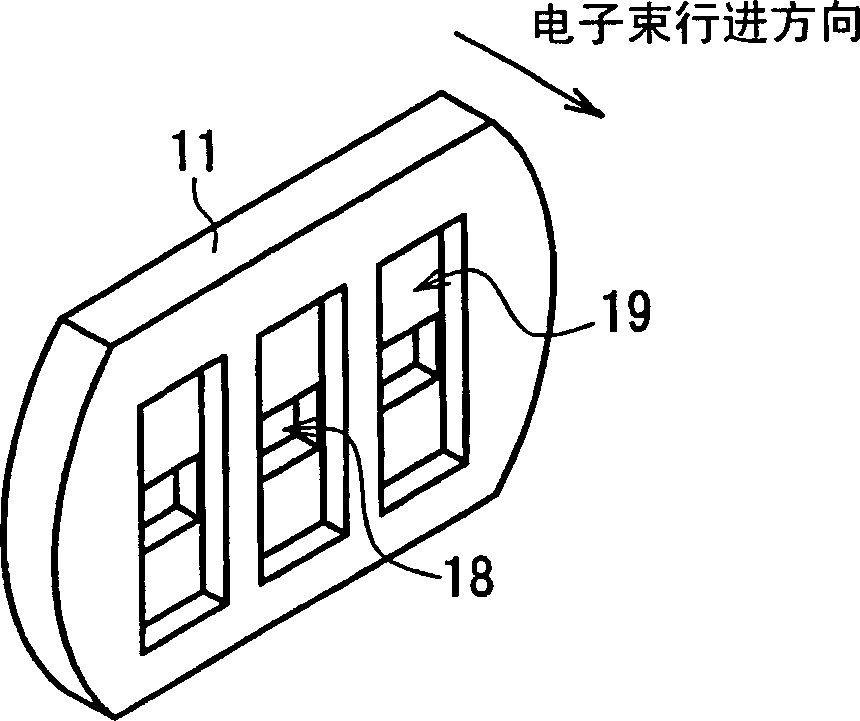
[0054] Figure 1A is a schematic horizontal cross-sectional view of the electron gun structure, Figure 1B is a schematic vertical sectional view of the electron gun structure. figure 2 is a schematic perspective view of the first grid structure of the electron gun. image 3 is a schematic perspective view of the second grid ...

Embodiment 2

[0069] In Embodiment 2, a color cathode ray tube apparatus including a second field correction electrode which is a sheet electrode having three apertures corresponding to three electron beams will be described with reference to FIGS. 7 and 8 . It should be noted that the color cathode ray tube device of this embodiment has the same structure as the color cathode ray tube device of Embodiment 1 described above, except for the structure of the second field correction electrode in the electron gun. Therefore, the same structural components are denoted by the same reference numerals, and descriptions thereof are omitted.

[0070] Figure 7A is a schematic horizontal cross-sectional view of the electron gun structure, Figure 7B is a schematic vertical sectional view of the electron gun structure. Figure 8 is a schematic translucent perspective view of the partial structure of the fourth grid and the second field correction electrode.

[0071] The second field correcting elect...


PUM


Abstract

A color cathode ray tube apparatus includes: a valve; a phosphor screen; an electron gun including an electron beam generating portion for generating three electron beams, a focusing electrode, an anode electrode, a first field correction electrode and a second field correction electrode; and a deflector for deflecting the electron beams emitted from the electron gun, wherein the focusing electrode, the first field correction electrode, the anode electrode and the second field correction electrode form an electron lens having a focusing force in a vertical direction, which is perpendicular to the horizontal direction, stronger than its focusing force in the horizontal direction inside the focusing electrode, and having a diverging force in the vertical direction greater than its diverging force in the horizontal direction inside the anode electrode, by applying a focus voltage to the focusing electrode and the first field correction electrode and applying an anode voltage higher than the focus voltage to the anode electrode and the second field correction electrode.

Description

technical field [0001] The present invention relates to color cathode ray tube devices. More particularly, the present invention relates to electron guns suitable for color cathode ray tubes. Background technique [0002] A typical conventional color cathode ray tube device will be described below with reference to FIG. 11. FIG. Fig. 11 is a horizontal sectional view showing the overall structure of a color cathode ray tube device. As shown in FIG. 11, the color cathode ray tube device has a vacuum tube composed of a panel 1 and a funnel 2 bonded together, and a shadow mask 3, a fluorescent screen 4 and an electron gun 6 provided in the inner space of the vacuum tube. In addition, a deflection yoke 8 is provided on the outer periphery of the vacuum tube. The fluorescent screen 4 includes three color fluorescent layers formed on the inner surface of the panel 1 to emit red, green, and blue light, respectively. The electron gun 6 is provided in the inner space of the neck ...

Claims


Application Information

Patent Timeline
Patent Type & Authority Applications(China)
IPC IPC(8): H01J29/48H01J29/50H01J31/20
CPCH01J2229/481H01J29/48H01J2229/4817H01J29/503H01J2229/4875H01J31/206H01J29/488
Inventor 上野博文和田恭典友安裕之森本泰治石原智成武川勉西山耕司
Owner MATSUSHITA TOSHIBA PICTURE DIS
Learn More