
Hydroelectric power generating apparatus

A power generation device and water conservancy technology, which is applied in the direction of hydroelectric power generation, machines/engines, impact engines, etc., can solve problems such as vibration and swing of water turbines, cavitation erosion of water turbines, uneven force on blades of water turbine impellers, etc.

Inactive Publication Date: 2005-12-21
郭联升
View PDF0 Cites 13 Cited by
  • Summary
  • Abstract
  • Description
  • Claims
  • Application Information

AI Technical Summary

Problems solved by technology

The disadvantages of this hydroelectric power generation device are: 1. The blades of the water turbine impeller are under uneven force, and the water turbine is prone to vibration and swing; 2. The water turbine is likely to cause cavitation; 3. The utilization rate of water conservancy and water energy resources is low

Method used


Image

  • Hydroelectric power generating apparatus
  • Hydroelectric power generating apparatus
  • Hydroelectric power generating apparatus

Examples


Embodiment Construction

[0013] The hydropower generation device of the present invention will be further described in detail below in conjunction with specific implementation methods and accompanying drawings.

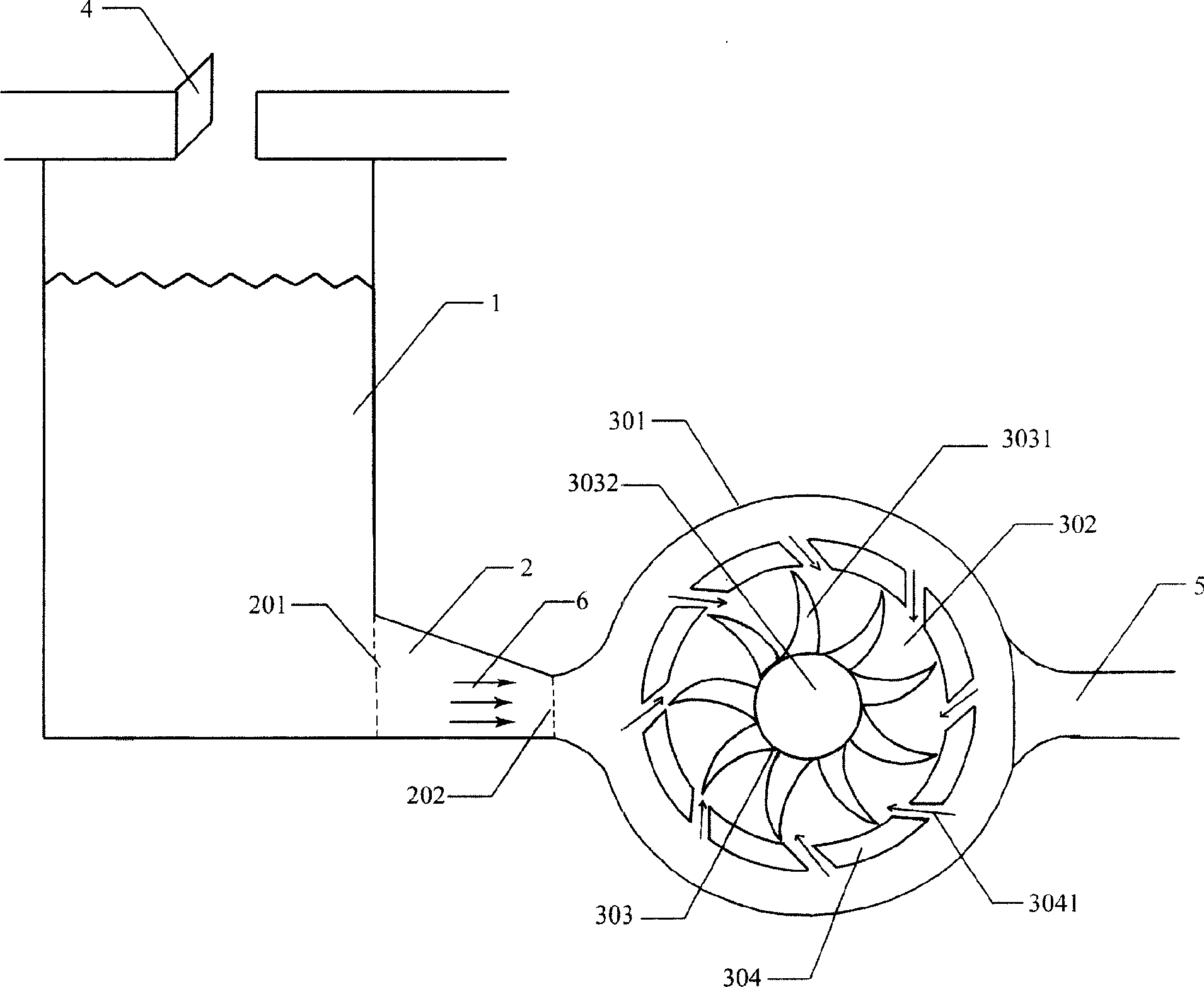
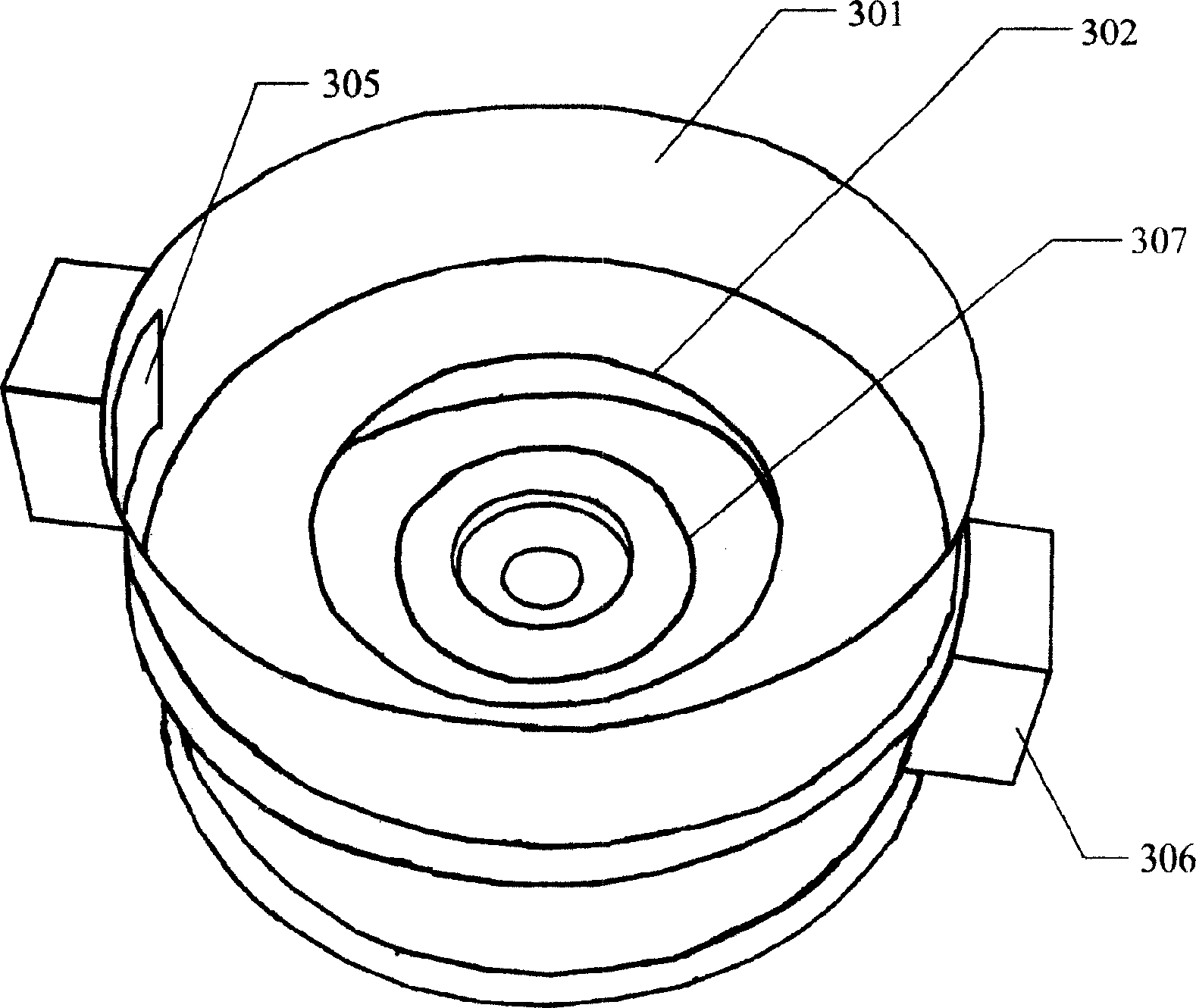
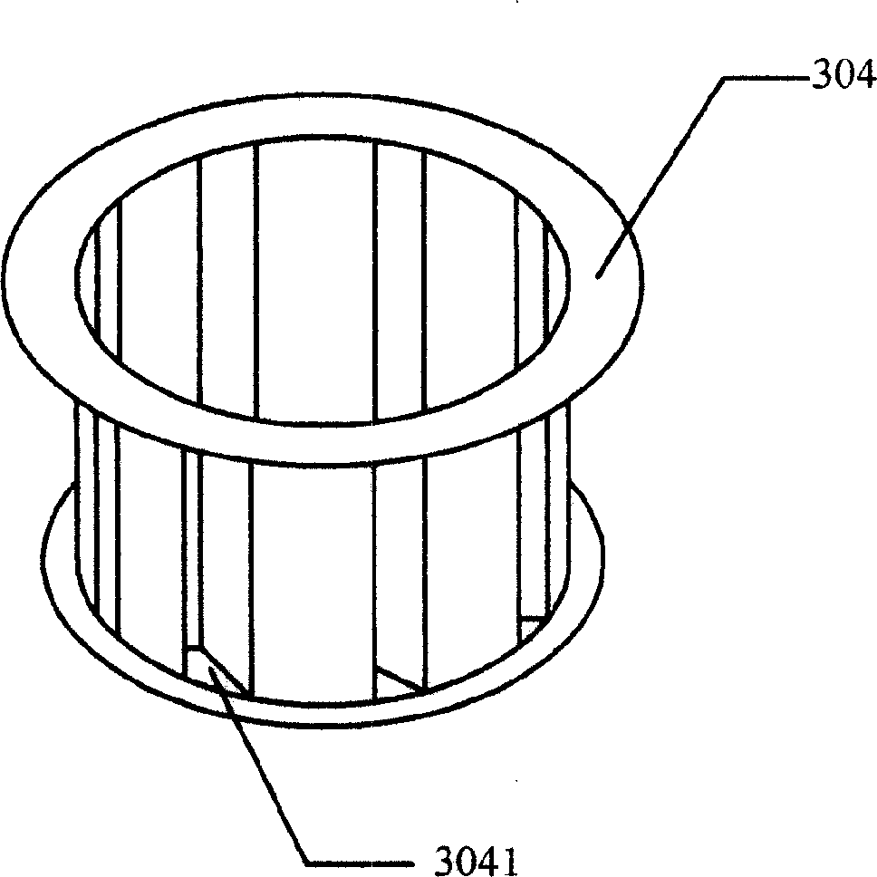
[0014] figure 1 It is a schematic diagram of the principle of a specific implementation of the hydroelectric power generation device of the present invention. In the figure, the hydroelectric power generation device also includes a water pool 1 with scaling and pressurization, and a water inlet culvert 2 with a scaling and pressurization function is built at its lowermost end. Its water inlet 201 communicates with the pool 1, and its water outlet 202 communicates with The water turbine volutes 301 are connected. In this embodiment, the flow area of ​​the water inlet end 201 of the water inlet culvert 2 is larger than the flow area of ​​the water outlet end 202. After the water flows through the water inlet culvert 2, the flow velocity has been scaled and increased, and the flow surface unit ...


PUM


Abstract

The invention discloses a kind of waterpower dynamotor. The machine shell includes two layers between which there are hatches in the partition. The impellor is in it. The lamina of the impellor is columnar, whose cross section is arc. Outside the lamina is the power water lamina, which is hollow columnar. Above the shell there is the entrance of water linking with the hole of water-in. the below layer is linking with the water-out hole. Waste comes in between them from the water-in hole, then flows into the lamina, pushing the lamina, and then flows out from the circle hatch. Because of the power of water pushing is from everywhere which is even, the lamina can be smooth when operating, so it avoids the phenomenon of librations and swings.

Description

technical field [0001] The invention relates to a power generating device, in particular to a hydropower generating device. Background technique [0002] The hydropower generation device in the prior art includes several parts such as a water inlet culvert, a water turbine volute, a water turbine impeller, a generator set, and a water outlet culvert. One end of the intake culvert is connected to the upstream dam, and the other end is connected to the volute of the water turbine. The vortex of the water turbine is cylindrical, and the center of the water turbine is equipped with a water turbine impeller. This kind of hydroelectric power generation device uses the weight of water itself and the drop to generate electricity. Water enters the turbine volute from the inlet culvert, impacts directly on the blades of the turbine impeller from one side, and flows into the outlet culvert to be discharged downstream after doing work. The disadvantages of this hydropower generation d...

Claims


Application Information

Patent Timeline
Patent Type & Authority Applications(China)
IPC IPC(8): F03B1/00
CPCY02E10/20Y02E60/16
Inventor 郭联升
Owner 郭联升
Learn More