Bearing-free switch magnetic-resistance starting generator and control method

A starter generator and switched reluctance technology, applied to the shape/style/structure of winding conductors, can solve the problems of limited application range of switched reluctance motors, motor torque ripple, electromagnetic noise, etc., to improve reliability and High-speed adaptability, reduce motor noise and torque ripple, and reduce mechanical wear

Inactive Publication Date: 2005-12-21
NANJING UNIV OF AERONAUTICS & ASTRONAUTICS
View PDF0 Cites 38 Cited by
  • Summary
  • Abstract
  • Description
  • Claims
  • Application Information

AI Technical Summary

Problems solved by technology

Due to the double salient pole structure of the stator and rotor of the switched reluctance motor, the torque ripple and

Method used


Image

  • Bearing-free switch magnetic-resistance starting generator and control method
  • Bearing-free switch magnetic-resistance starting generator and control method
  • Bearing-free switch magnetic-resistance starting generator and control method

Examples


Embodiment Construction

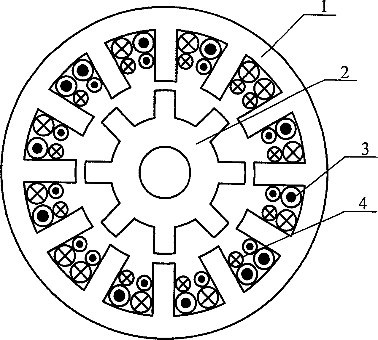
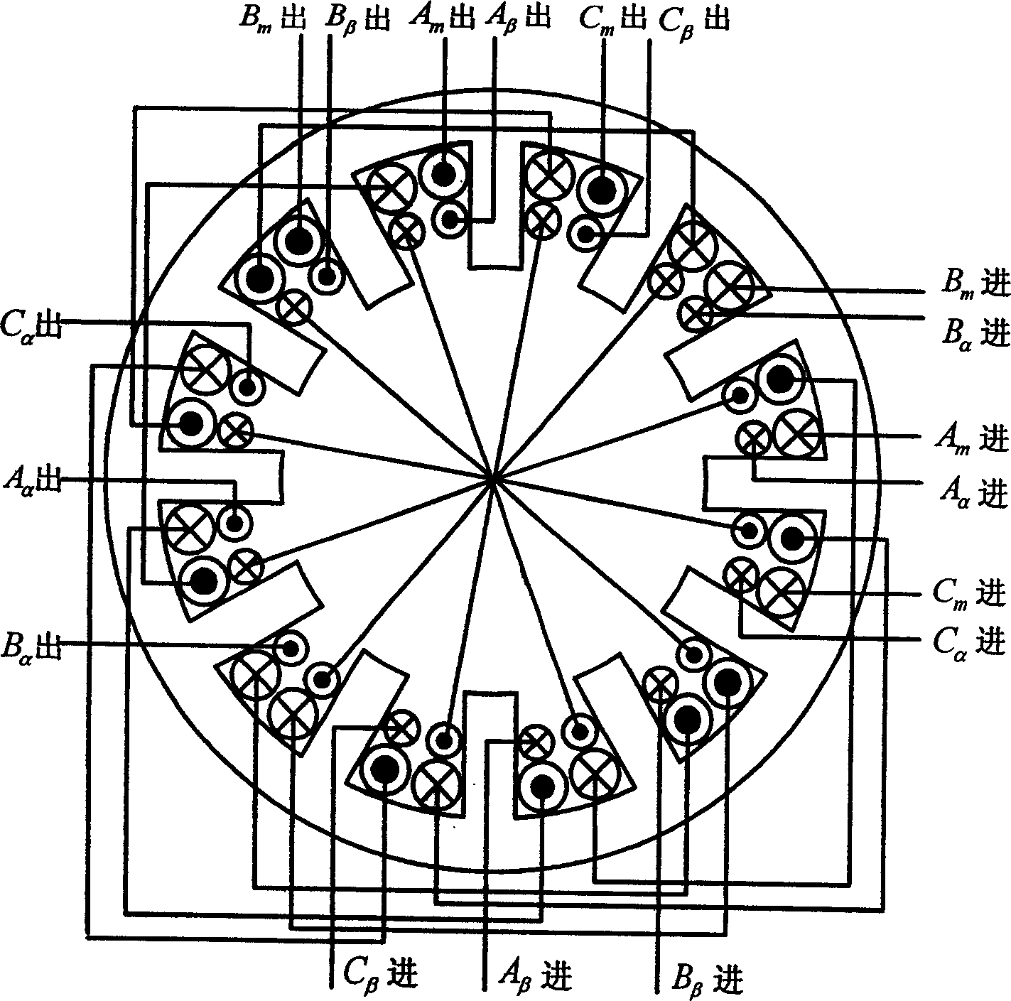
[0018] The schematic structural diagram of the bearingless switched reluctance starter generator shown in Fig. 1 is a cross-sectional schematic diagram of a bearingless switched reluctance motor with a 12 / 8 structure. The motor of the present invention includes a stator 1 and a rotor 2 without windings. It is characterized in that the teeth of the stator 1 are embedded with a concentrated torque winding 3 and a suspension winding 4 at the same time, and the power converter of the torque winding adopts a three-phase asymmetrical half-bridge topology circuit. structure, the power converter of the suspension winding adopts a three-phase four-leg topology circuit structure. Figure 2 is a schematic diagram of the connection between the torque winding and the suspension winding of a bearingless switched reluctance starter generator with a 12 / 8 structure. A phase torque winding A in Figure 4 m , by A m In turn, the four torque windings of phase A are connected in series to A m out...


PUM


Abstract

The generator includes stator, rotor without winding. Torsion winding and suspension winding are sheathed on the stator. Torsion winding implements the functions of starting up and generating electricity. Superposing magnetic field generated by suspension winding on bias magnetic field generated by torsion winding produce variable lift force so as to realize stable suspension of rotor. Current control method of torsion winding includes following three modes: current chop, modulation of angle position and pulse width modulation. Synthesizing the said three modes, four methods for controlling suspension are adopted in the invention to calculate given suspension current value. Integrating roles of starter, generator and magnetic bearing, the disclosed generator possesses wide application and important meaning in areas of aviation and spaceflight.

Description

1. Technical field [0001] The invention relates to a bearingless switched reluctance starter generator and a control method thereof, which belong to a motor-type switched reluctance starter generator. 2. Background technology [0002] The current switched reluctance starter generator has the advantages of simple structure, firmness, low cost, reliable operation, flexible control, high operating efficiency, strong fault tolerance, and high temperature and high speed adaptability. However, the wear of the mechanical bearings caused by the high-speed operation of the rotor is aggravated, which shortens the service life of the bearings and the motor, and also increases the burden of maintenance on the motors and bearings. Due to the double salient pole structure of the stator and rotor of the switched reluctance motor, the torque ripple and electromagnetic noise of the motor are caused, which also limits the application range of the switched reluctance motor. 3. Contents of th...

Claims


Application Information

Patent Timeline
IPC IPC(8): H02K3/28
Inventor 邓智泉杨钢曹鑫王晓琳
Owner NANJING UNIV OF AERONAUTICS & ASTRONAUTICS
Why Eureka
Try Eureka