Knob mechanism structure of drum washing machine

A drum washing machine and knob technology, applied in the field of washing machines, can solve the problems of ineffective prevention of the damage of the rotary switch 5, reduced operation accuracy of the knob, and large loosening of the knob 50, so as to prevent damage, improve trust, and reduce the loosening of the left and right. Effect

Inactive Publication Date: 2006-01-04
LG ELECTRONICS (TIANJIN) APPLIANCES CO LTD
View PDF0 Cites 6 Cited by
  • Summary
  • Abstract
  • Description
  • Claims
  • Application Information

AI Technical Summary

Problems solved by technology

[0016] First of all, although the existing illuminator bracket 6 can prevent the light leakage of the illuminator (L), it is only limited to this function and cannot effectively prevent the rotary switch 5 from being damaged when it is impacted by the side.
[0017] That is, the existing illuminator bracket 6 simply supports the illuminator (L) and prevents the light from leaking from the illuminator (L), but cannot prevent the rotary switch 5 from being damaged when the knob 50 is subjected to an impact force in the side direction.
[0018] In addition, in the existing knob mechanism, the left and right looseness of the knob 50 is large, so the user feels uncomfortable when operating it.
Not only that, but also reduces the accuracy of the knob operation

Method used


Image

  • Knob mechanism structure of drum washing machine
  • Knob mechanism structure of drum washing machine
  • Knob mechanism structure of drum washing machine

Examples


Embodiment Construction

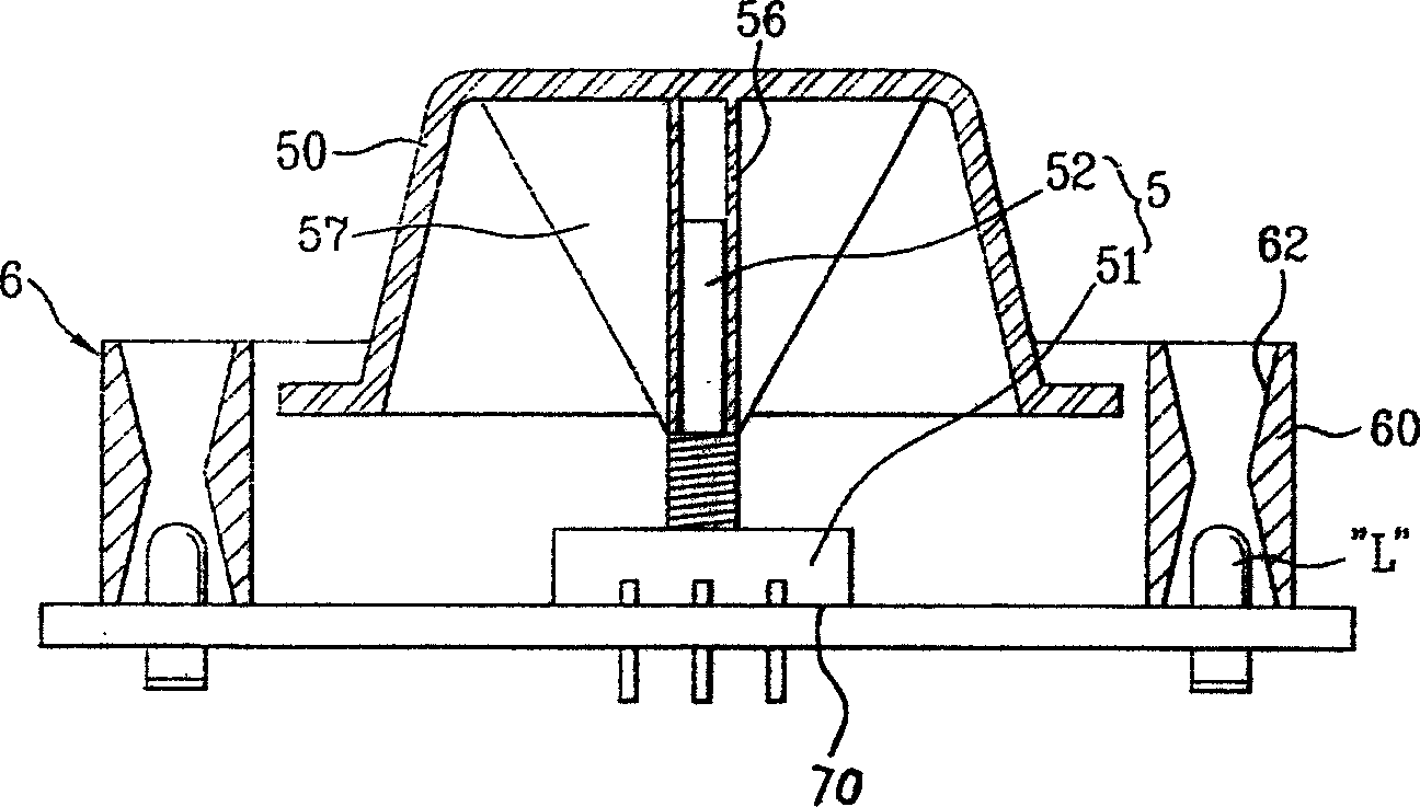
[0045] Below in conjunction with accompanying drawing and specific embodiment the present invention is described in further detail: Figure 5 It is a sectional view of the knob mechanism of the present invention. Image 6 Yes Figure 5 The bottom view of the knob in .

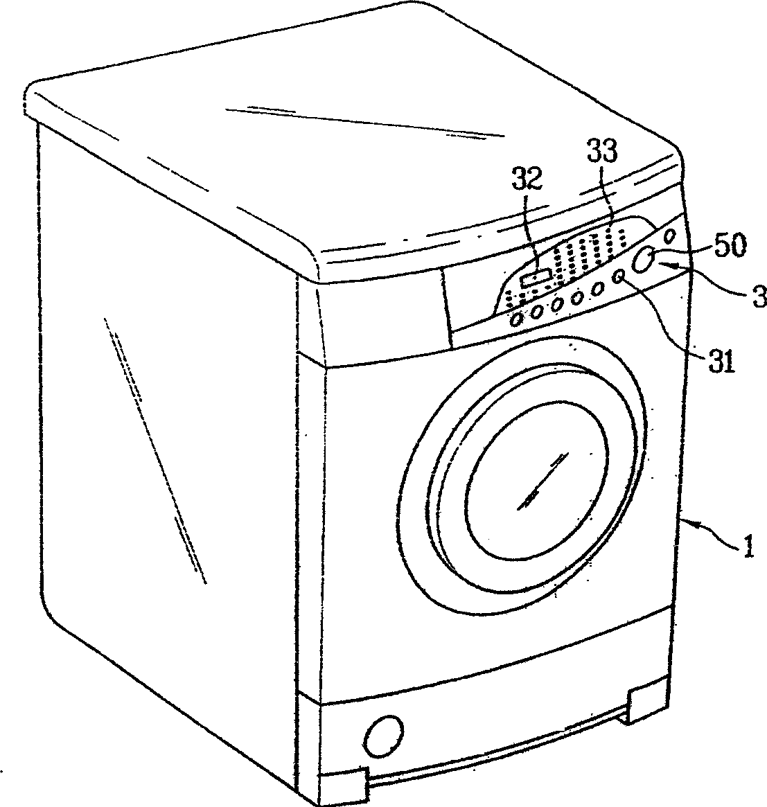
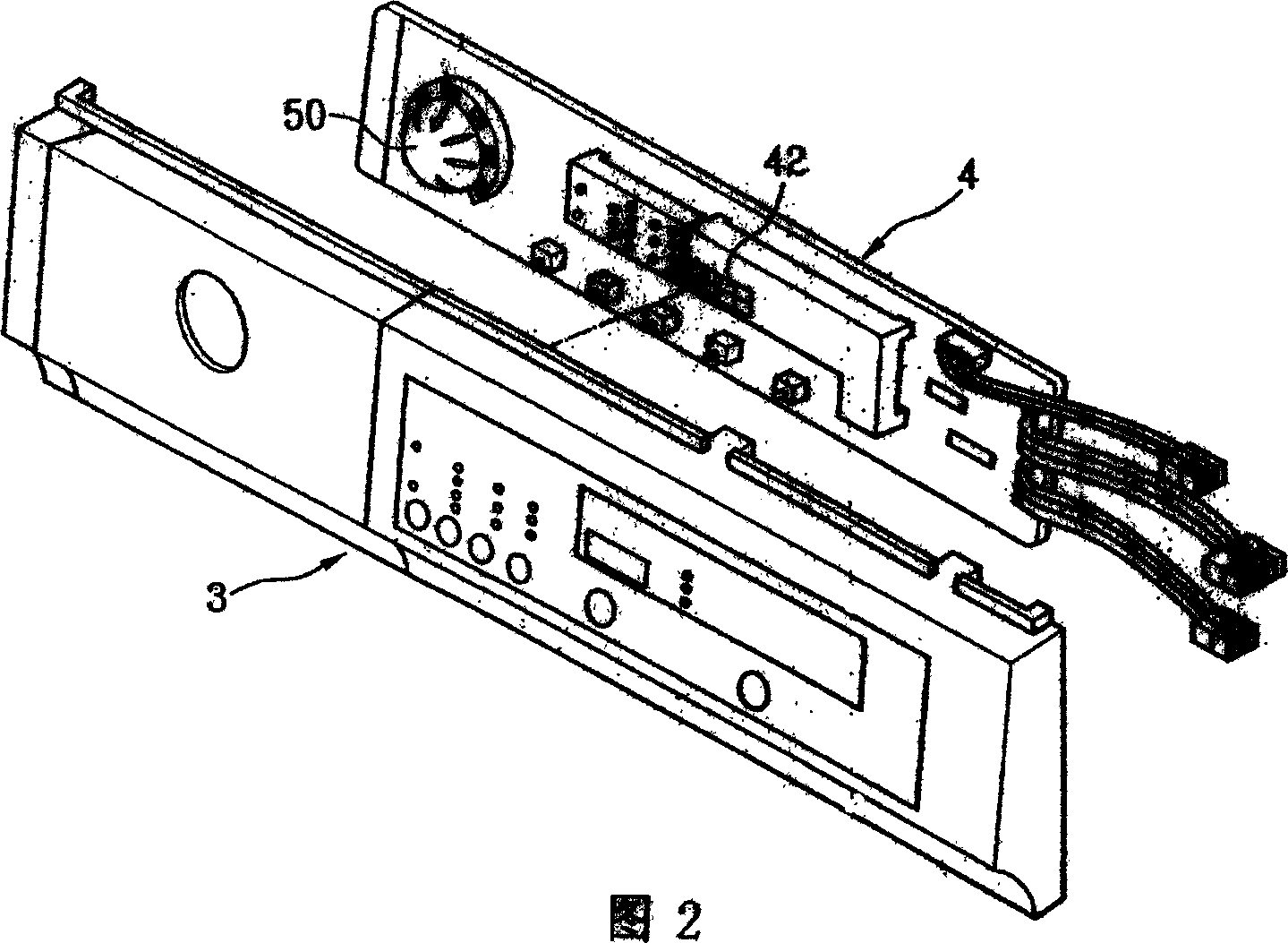
[0046] As shown in the figure, the knob mechanism of the drum washing machine of the present invention is a rotary switch 5 composed of an encoder 51 fixed on the circuit board 70 and an encoder shaft 52 connected to the encoder 51; The insertion sleeve 56 of the encoder shaft 52 and the knob 50 constituted by the reinforcing ribs for strengthening the insertion sleeve 56 strength; the ring-shaped illuminator bracket 6 that surrounds the knob 50 and is fixed on the circuit board 70 is formed.

[0047] In the drum washing machine knob mechanism of the present invention composed of the above-mentioned components, the inner side of the main frame 60 of the illuminator bracket 6 is provided with a shaft supportin...


PUM


Abstract

The knob mechanism structure of drum type washing machine includes rotary switch comprising coder fixed to the circuit board and connected coder shaft; knob including the shaft sleeve inserted into the coder shaft and reinforcing ribs for the shaft sleeve; and ring lighting unit rack surrounding the knob and fixed on the circuit board. Inside the lighting unit rack, there are shaft supporting flange and shaft sleeve around the central hole of the shaft supporting flange, and the shaft sleeve extends to inside of the knob to support the outside of the coder shaft and the reinforcing ribs outside the shaft sleeve. The present invention can avoid the loosing of the knob mechanism and the damage of rotary switch caused by side impact.

Description

technical field [0001] The invention relates to the field of washing machines. Background technique [0002] Generally speaking, the washing method of the drum washing machine is: put washing powder, tap water and laundry into the drum, use the rotational force provided by the motor to rotate the drum and the laundry, and remove the dirt from the laundry through the mutual friction between the drum and the laundry. Therefore, the washing method of the drum washing machine hardly damages the laundry, and the laundry will not be entangled with each other, and the washing effect of the drum washing machine is very good. [0003] figure 1 It is a three-dimensional view of the appearance of a general front-loading washing machine. As shown in the figure, the appearance of the drum washing machine is roughly a cuboid with a door formed on the front. The laundry can be put into the drum through the door, or the cleaned clothes can be taken out from the drum. [0004] There is a...

Claims


Application Information

Patent Timeline
IPC IPC(8): D06F37/00
Inventor 金臣李奉相
Owner LG ELECTRONICS (TIANJIN) APPLIANCES CO LTD
Why Eureka
Try Eureka