

Rotation supporting mechanism and portable terminal
A technology of rotating support and axial support, which is applied in the direction of telephone structure, building structure, construction, etc.
- Summary
- Abstract
- Description
- Claims
- Application Information
AI Technical Summary
Problems solved by technology
Method used
Image

Examples
Embodiment 1
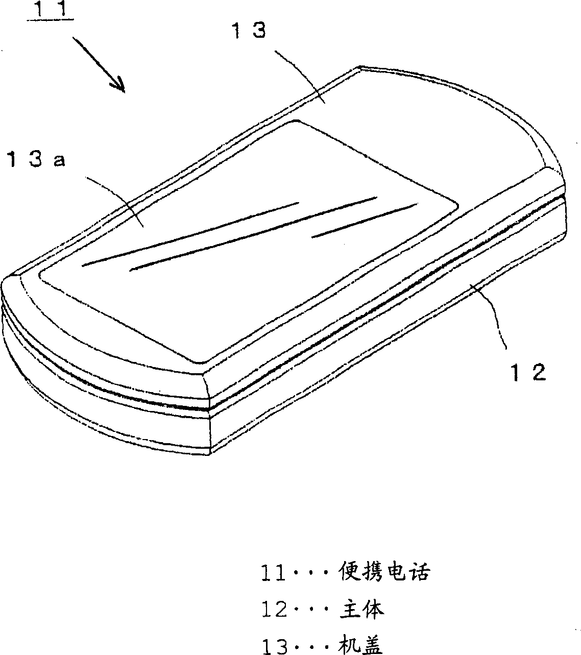
[0109] figure 1 As an example in which the rotation supporting mechanism is applied to a portable telephone, this example will be described with reference to the accompanying drawings.
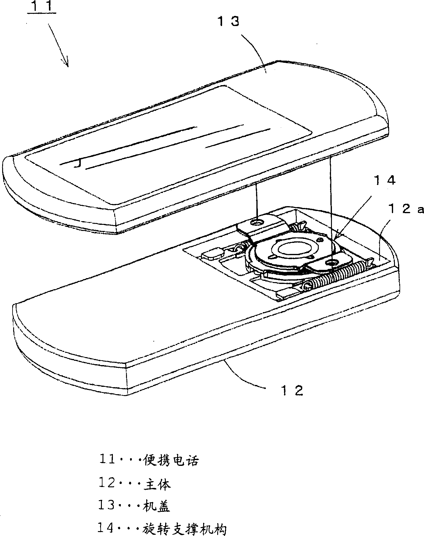
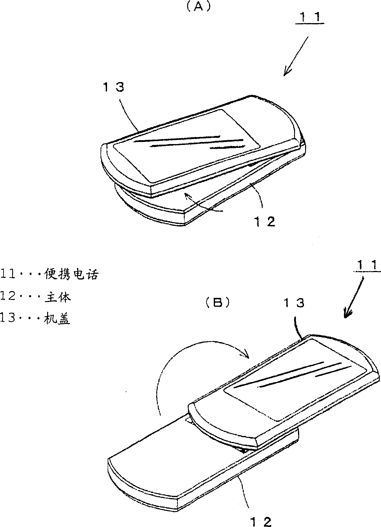
[0110] figure 1 A portable telephone of a horizontal rotation type is shown. The portable phone 11 of this horizontal rotation type is designed as a horizontal rotation type in which a rectangular plate-like main body 12 and a cover 13 of the same shape are stacked so that they can be opened and closed in a planar direction, and the cover 13 are rotated in the planar direction, and in this direction they are also superimposed.
[0111] Outer surfaces such as the upper and side surfaces of the main body 12 and the cover 13 are equipped with a display screen, an input device and an antenna (not shown) to utilize various electronic information including telephone and e-mail .
[0112] Such as figure 2 As shown in , during the connection process between the main body 12 and the cover 13 , ...
Embodiment 2
[0152] Figure 14 Embodiment 2 of the rotating support mechanism is shown. Since this rotary support mechanism 141 has the same structure as the rotary support mechanism 14 described in Embodiment 1 except for the pressing structure, only the different pressing structures will be described.
[0153] The compression structure of the rotary support mechanism 141 is composed of a helical compression spring 142 combined with a tilting lever 144 provided with a pressing roller 143, and the lever uses the principle of leverage.
[0154] The use of the compression spring 142 reduces the number of components. The elongated helical compression spring 142 is connected to the tilting lever 144 by hooking the base end portion of the compression spring 142 to a spring claw portion protrudingly disposed on a corner of the base member 145. 145a, and hook its free end side to the free end side of the tilting lever (to be described below), the free end side of the spring can extend and contr...
Embodiment 3
[0158] Figure 15 and Figure 16 Embodiment 3 of the rotation support mechanism 152 provided in the horizontal rotation type mobile phone 151 is shown. The rotation support mechanism in embodiment 3 has the same function as the rotation support mechanism 14 in embodiment 1 already described, except that the anti-swing function of the machine cover and the tilting guide function of the slider are improved. Therefore, only the different parts are described.
[0159] This rotation support mechanism 152 is connected to a position where the main body 153 and the cover 154 facing each other are vertically connected so as to axially support them in the direction in which they are stacked. The axial support position of the rotation support mechanism 152 is set at a side where the base end portions 153a, 154b of the main body 153 and the cover 154 are located, and this side corresponds to one of the stacked main body 153 and the cover 154 in the closed position. Longitudinal side se...
PUM
 Abstract
Description
Claims
Application Information