Imbedded joining device of pushing ship and barge

A technology of a coupling device and a jacking vessel, which is applied to tugboats and other directions, can solve problems such as huge loads, damage to the hull of a jacking vessel and a barge, and achieve the effects of low manufacturing cost, good self-positioning ability, and simple and reliable coupling device.

Inactive Publication Date: 2006-01-11
武汉思诺泰科技有限公司
View PDF0 Cites 4 Cited by
  • Summary
  • Abstract
  • Description
  • Claims
  • Application Information

AI Technical Summary

Problems solved by technology

However, in the case of relatively large wind and waves, the coupling device between the pusher ship and the barge will bear a huge load, resulting in damage to the hull of the pusher ship and barge

Method used


Image

  • Imbedded joining device of pushing ship and barge
  • Imbedded joining device of pushing ship and barge
  • Imbedded joining device of pushing ship and barge

Examples


Embodiment Construction

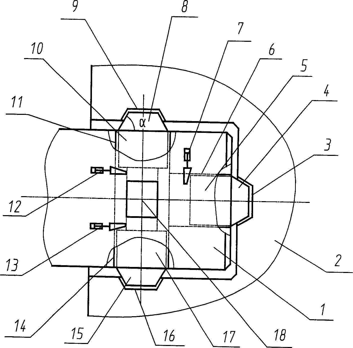
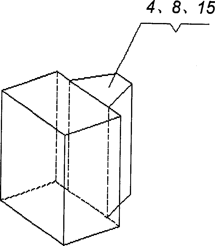
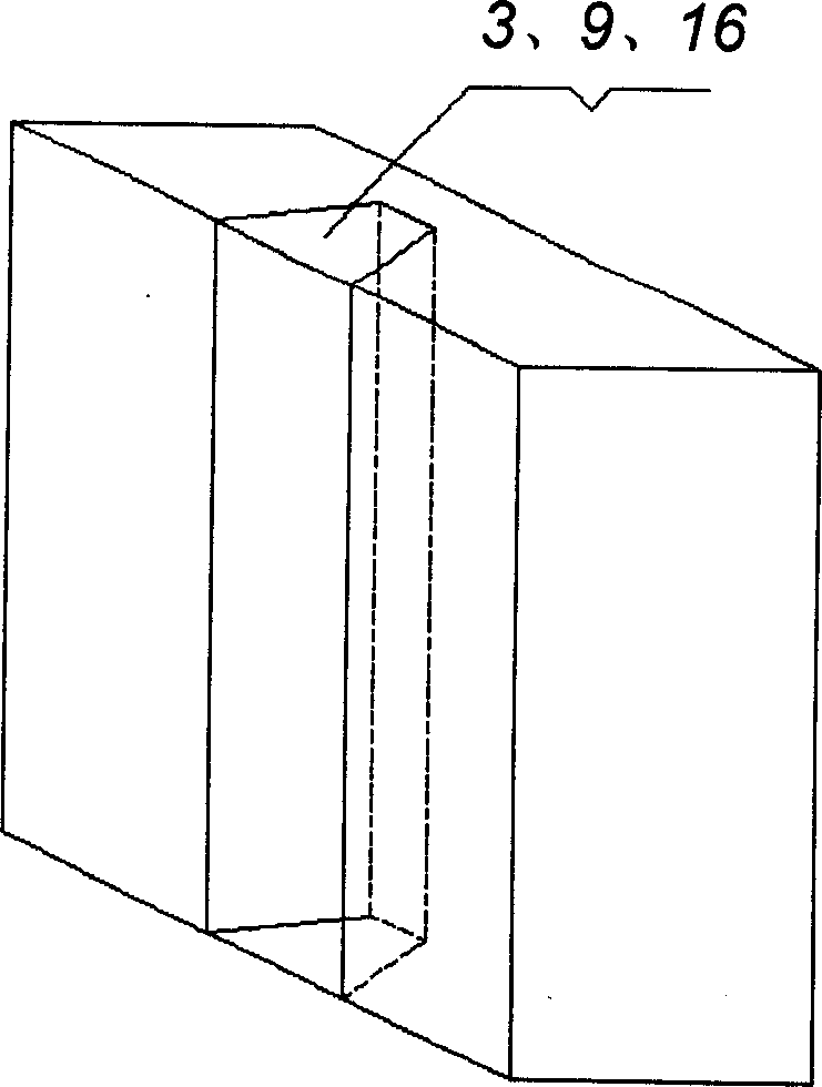
[0014] like figure 1 As shown, the present invention is an embedded coupling device for a pusher ship and a barge. There is a fitting recess 3 on the central symmetrical axis of the main concave part of the barge 2, and a fitting convex part 4 is arranged on the central symmetrical axis of the bow of the pusher ship 1. , two fitting convex parts 8, 15 are symmetrically arranged on the left and right sides of the pusher ship 1, and there are two fitting concave parts 9, 16 on the main concave part of the symmetrical barge 2. The device also has hydraulic power drive, locking devices 5, 10, 17 and mechanical secondary locking devices 7, 12, 13, hydraulic system 18, control system and the like. Wherein the hydraulic power drive, locking devices 5, 10, 17 and mechanical secondary locking devices 7, 12, 13 are connected with the hydraulic system 18 through hydraulic pipelines, and the control system is connected with the hydraulic system through corresponding cables.

[0015] The ...


PUM


Abstract

An embedded coupling between the pushing ship driven by engine and the barge features that the main recess on the central axis of barge has two embedding recesses, said pushing ship has three convex parts respectively positioned on its central axis and both sides, said convex part is pivoted with the push rod of hydraulic power unit, and the cylinder of said hydraulic power unit is fixed to said pushing ship.

Description

technical field [0001] The invention relates to a ship device, more specifically to an embedded coupling device for a pusher ship and a barge. Background technique [0002] According to the literature search, it is known that the coupling devices for pusher boats and barges are produced by many companies such as Finland and Japan abroad, and the more representative ones are the solutions of ACOMARIN Company of Finland and Murata Company of Japan. [0003] ACOMARIN Company of Finland uses a two-point connection. Each connection point pushes the ship using a single cylindrical pin, and the barge adopts a series of wedge-shaped slideways with round holes. One wedge-shaped slideway corresponds to a round hole. [0004] When the push boat enters the concave part of the barge, the single cylinder pin on the push boat will continue to protrude from the hull under the action of the hydraulic cylinder, slide along the wedge-shaped slideway on the barge, and f...

Claims


Application Information

Patent Timeline
Patent Type & Authority Applications(China)
IPC IPC(8): B63B35/70
Inventor 聂松林张钰桥
Owner 武汉思诺泰科技有限公司
Why Eureka
Try Eureka