Position referencing system

A reference system and detection device technology, applied to measuring devices, optical devices, instruments, etc., can solve problems such as poor performance-to-cost ratio

Inactive Publication Date: 2006-01-11
OTIS ELEVATOR CO
View PDF0 Cites 16 Cited by
  • Summary
  • Abstract
  • Description
  • Claims
  • Application Information

AI Technical Summary

Problems solved by technology

In summary, one of the major problems in existing position reference systems is the poor performance-to-cost ratio

Method used


Image

  • Position referencing system
  • Position referencing system
  • Position referencing system

Examples


Embodiment Construction

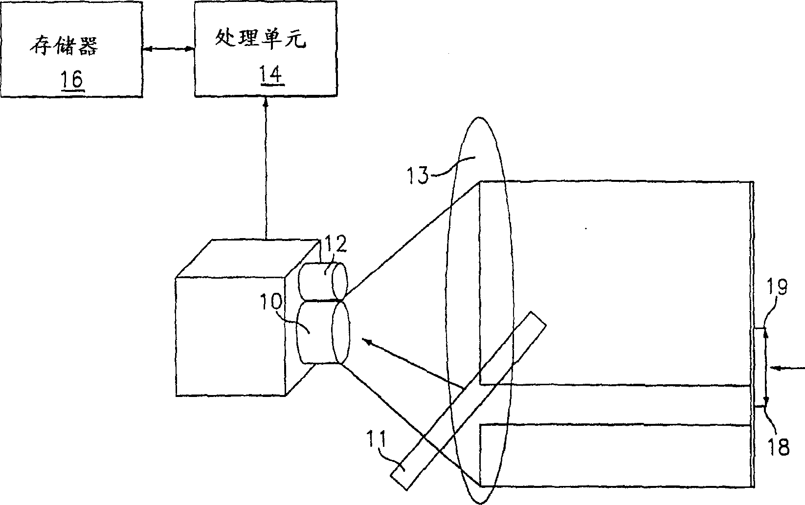
[0015] Referring now to the accompanying drawings, figure 1 Shows how a one-dimensional charge-coupled device (CCD) 10 based relative position reference system works. That is, the reflector 11 is illuminated by a light source or linear illumination source 12 . When the light is reflected by the reflector 11, a light image 13 is formed. The camera 10 is preferably a CCD sensing device that detects at least part of the light image 13 and converts the detected light image into an electrical signal that is transmitted to a processing unit 14 such as a pre-programmed computer and stored in a computer associated with the processing unit 14. in the memory 16. By using signal processing algorithms already programmed in the processing unit 14, the position of the center 18 of the reflector 11 relative to the center of the CCD device 10 can be calculated. The signal processing algorithm may comprise a sub-pixel resolved signal processing algorithm and may comprise any suitable algori...


PUM


Abstract

The present invention relates to a position referencing system and method for horizontal or vertical conveyance, e.g., an elevator. The position referencing system includes a plurality of spaced apart color elements or reflectors (42) attached to a static structure (40), such as a door frame in a hoistway or guideway, a light source (12) for illuminating one of the reflectors, and a sensing device (10, 48, 48') for capturing an image of the illuminated reflector. The image captured by the sensing device is used to determine the position and / or speed of the conveyance, e.g., an elevator car.

Description

technical field [0001] The present invention relates to a system and method of low cost and high performance absolute position referencing for elevators and other (passenger) conveyances such as horizontal passenger conveyance. Background technique [0002] A position reference system is a component of a control system that provides fast and accurate position measurement of an elevator car in an elevator hoistway or in a (passenger) car along a guideway. The speed and accuracy of the position reference system is determined by the given control system relative to ensuring a certain level of ride quality. One example is that position measurements should be made within 10 ms delay and with 1 mm accuracy. These performance requirements are very stringent in view of the wide operating range of the elevator (up to 500m) and the long distances between stops for (passenger) transport. In addition to performance requirements in terms of accuracy and measurement delay, for example m...

Claims


Application Information

Patent Timeline
Patent Type & Authority Applications(China)
IPC IPC(8): B66B1/34B66B3/00G01B11/14G01B11/03
CPCB66B1/3492
Inventor J・-H・欧P・康A・芬P・-Y・彭
Owner OTIS ELEVATOR CO
Why Eureka
Try Eureka