Device for increasing the functional reliability of a hydraulic circuit of a hydraulically operable clutch

A hydraulic circuit and hydraulic operation technology, applied in the direction of clutches, fluid-driven clutches, non-mechanical drive clutches, etc., can solve the problems of complex structure, easy-to-failure manufacturing, and high cost of pneumatic boosters, and achieve the goal of increasing operation and maintenance costs Effect

Inactive Publication Date: 2006-01-11
ZF FRIEDRICHSHAFEN AG
View PDF1 Cites 6 Cited by
  • Summary
  • Abstract
  • Description
  • Claims
  • Application Information

AI Technical Summary

Problems solved by technology

[0007] However, the pneumatic supercharger of the device has a complex structure and is prone to failure to a certain extent and is relatively expensive to manufacture.

Method used


Image

  • Device for increasing the functional reliability of a hydraulic circuit of a hydraulically operable clutch
  • Device for increasing the functional reliability of a hydraulic circuit of a hydraulically operable clutch
  • Device for increasing the functional reliability of a hydraulic circuit of a hydraulically operable clutch

Examples


Embodiment Construction

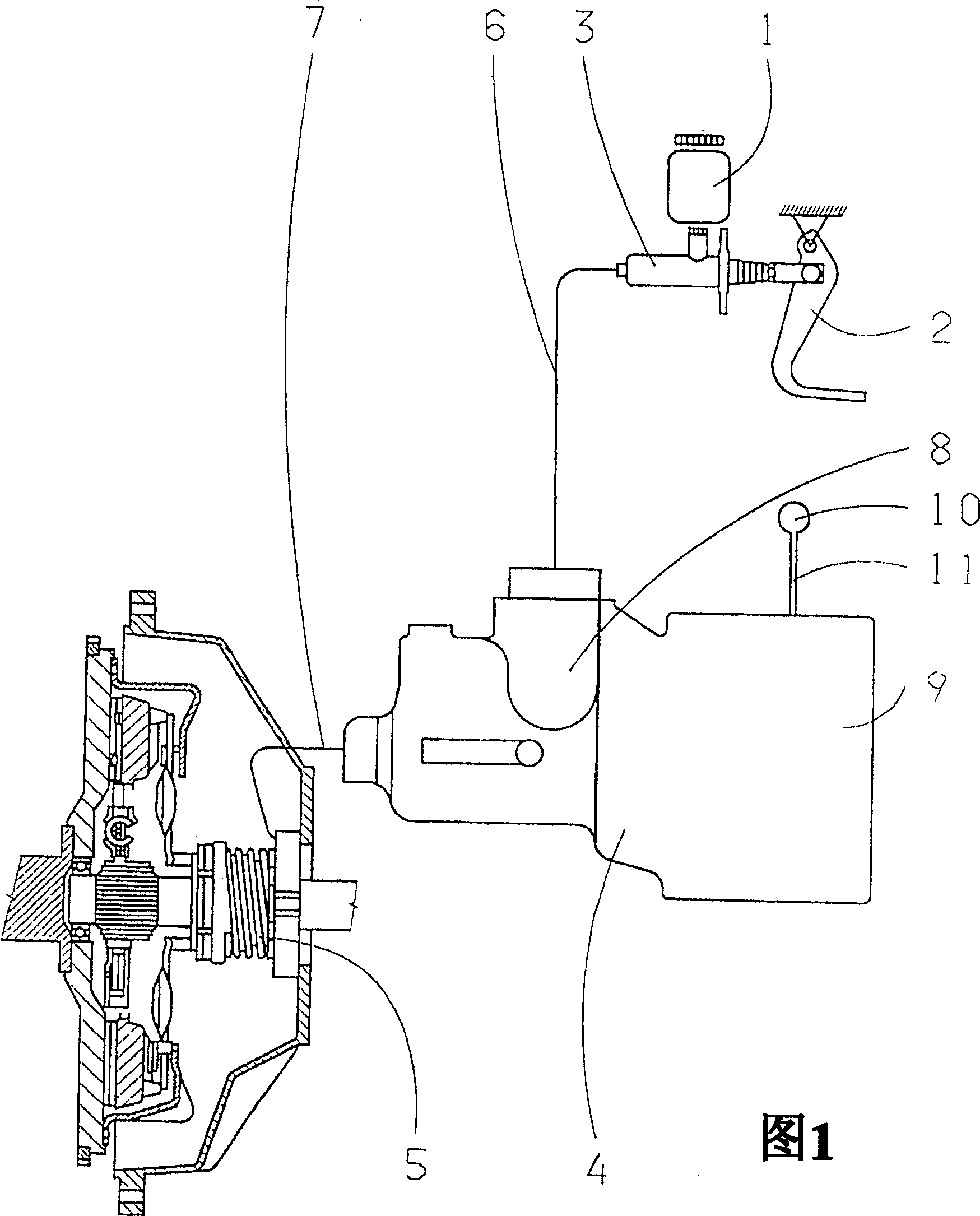
[0022] According to Figure 1, the hydraulic clutch control device with a pneumatic booster mainly includes: a transmitter cylinder 3 with a compensation container 1 and operated by a clutch pedal 2, a booster 4 behind the transmitter cylinder, and a clutch acting on the clutch release mechanism. The separating cylinder 5 and the hydraulic lines 6 and 7 , which create a fluid-tight connection between the transmitter cylinder 3 and the pressure booster 4 and between the pressure booster 4 and the separating cylinder 5 .

[0023] The booster 4 has a pneumatic zone 9 acting on the hydraulic zone 8 and the adjacent hydraulic lines 6 , 7 , which zone can be loaded with compressed gas in the activated state, supplied by an air compressor 10 via the pneumatic line 11 .

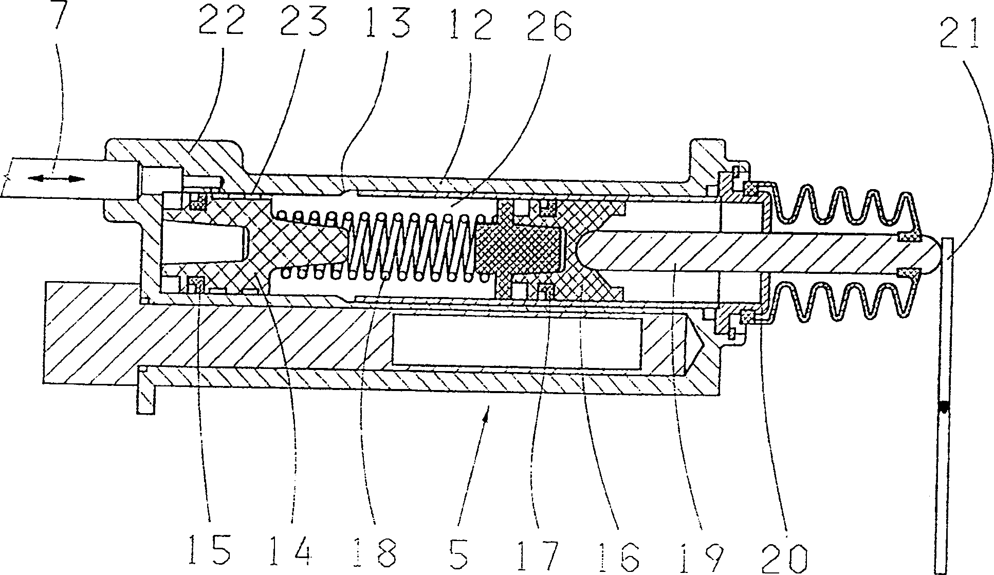
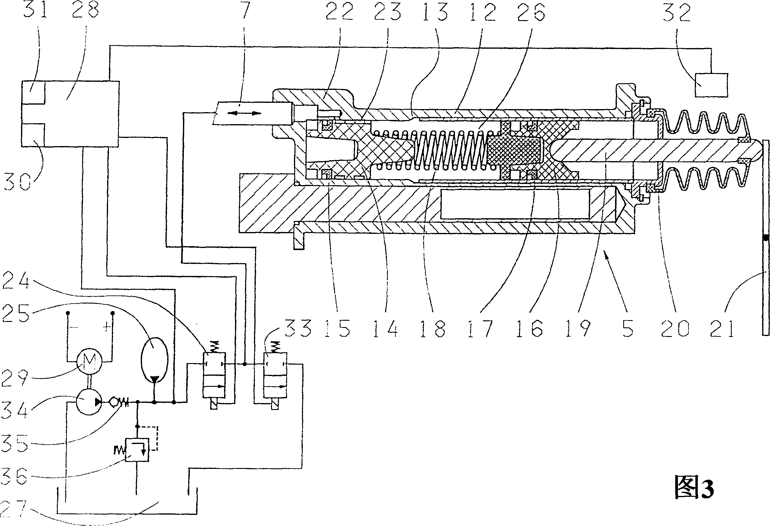
[0024] figure 2 The separating cylinder 5 is shown in the uncontrolled state. The substantially cylindrical housing 12 has a stepped bore 13 in which a primary piston 14 with a sealing ring 15 and a secondary piston ...


PUM


Abstract

In order to prevent an unintentional release of the clutch when the vehicle is at a standstill and the parking brake is released, the aim of the invention is to further develop a known device for increasing the functional reliability of a hydraulic circuit of a hydraulic clutch, comprising a pressure reservoir (25) and a release cylinder (5), which has a primary piston (14), a secondary piston (16) and a compensation volume. To this end, a pressure monitoring / supply device (28) is used that determines a reference operating pressure and sets a static pressure that, in the event of system faults, only permits the secondary piston (16) to be displaced such that the contact pressure of the clutch disks against one another is still sufficient to hold the vehicle at a standstill.

Description

technical field [0001] The invention relates to a device for increasing the functional reliability of a hydraulic circuit of a hydraulically actuated clutch according to claim 1 or the preamble of claim 7 . Background technique [0002] The purpose of increasing the functional reliability of the hydraulic circuit of the hydraulically operated clutch is also to maintain the current shifting state of the clutch and to achieve a defined transition characteristic between the shifting states, which is repeatable and acceptable to the driver of the vehicle concerned. Effective control. [0003] To meet these requirements, superchargers are known from the prior art, which provide sufficient feedback to the clutch pedal, so that the engagement and disengagement processes can be tailored to the prevailing situation by the driver. In this case it is all the more important to implement a backlash and wear compensation in order to ensure a coordinated operating characteristic over the ...

Claims


Application Information

Patent Timeline
Patent Type & Authority Applications(China)
IPC IPC(8): F16D48/06F16D25/08F16D48/02
CPCF16D48/066F16D25/088F16D48/02F16D25/14F16D2048/0275F16D2048/0203F16D2048/0212F16D2500/1024F16D2500/50825F16D2500/5104F16D2500/5114F16D2500/70406
Inventor 托马斯·克诺布劳赫克里斯托夫·鲁哈特奥托·埃布纳克劳斯·施魏格尔马蒂亚斯·温克尔安德烈亚斯·施文格尔马库斯·甘索尔
Owner ZF FRIEDRICHSHAFEN AG
Why Eureka
Try Eureka