Extrusion molding apparatus and extrusion molding method

A technology of extrusion molding and extrusion direction, which is used in ceramic molding machines, material molding presses, presses, etc., can solve problems such as complexity and reduce efficiency, and achieve the effect of reducing deformation force and preventing deformation.

Inactive Publication Date: 2006-01-18
DENSO CORP
View PDF1 Cites 2 Cited by
  • Summary
  • Abstract
  • Description
  • Claims
  • Application Information

AI Technical Summary

Problems solved by technology

The support at the front end and the operation of cutting by unit length also become complicated and thus reduce the efficiency

Method used


Image

  • Extrusion molding apparatus and extrusion molding method
  • Extrusion molding apparatus and extrusion molding method
  • Extrusion molding apparatus and extrusion molding method

Examples


Embodiment 1

[0048] see Figures 1 to 5 , the extrusion molding device and extrusion molding method according to the embodiments of the present invention will be described in detail below.

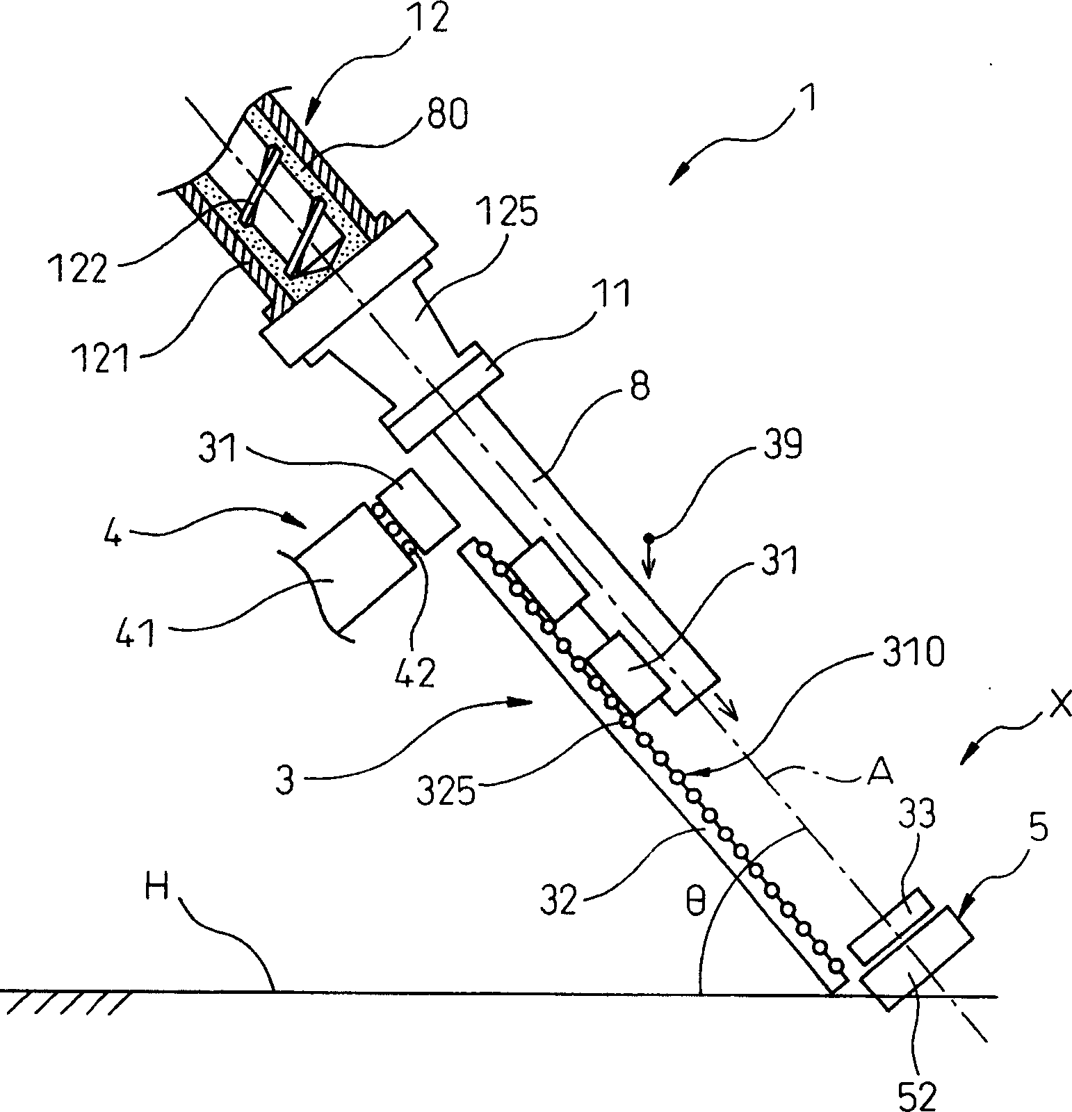
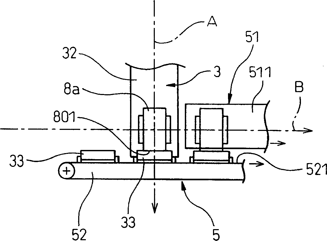
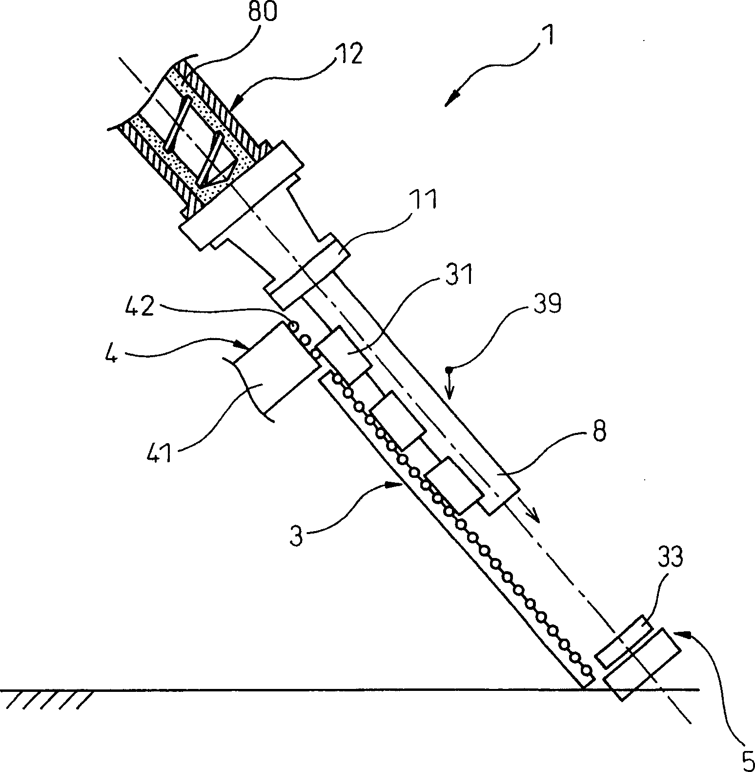
[0049] Such as figure 1 As shown, the extrusion molding device 1 of the present embodiment includes a screw extruder 12 and a conveying device 3; The conveying device 3 supports the extruded molded body 8 continuously extruded from the screw extruder 12, and conveys the extruded molded body 8 along the extrusion direction.

[0050] The screw extruder 12 has an inclination angle θ between the extrusion axis A and the horizontal axis H, which ranges from 15° to 85°. The conveying device 3 is configured such that in a direction substantially parallel to the extrusion axis A, the receiving table 31 which supports the extruded material extruded along the extrusion axis A on the outer peripheral surface (of the extrusion molded body 8 ) is moved. Molded body 8.

[0051] This will be explained in more de...

Embodiment 2

[0074] In this example, if Figure 6 As shown, the structure of the conveying device 3 is modified from the extrusion molding device 1 in Example 1.

[0075] Therefore, the conveying device 6 of this embodiment adopts belt conveyors 61 and 62 instead of the above-mentioned conveyor 32 composed of roller conveyors. Each belt conveyor 61 , 62 has a conveying surface 611 , 621 respectively, each intended to accommodate a receiving table 31 arranged substantially horizontally to the axis A of extrusion. A plurality of stoppers 612, 622 are provided on the conveying surfaces 611, 612 by which the receiving table 31 is supported on its front end face in the direction of movement; and the stoppers are constructed such that the continuous supply to the conveyor The receiving table 31 can be continuously supported by the stoppers 612, 622 and can move forward.

[0076] The belt conveyor 61 on the upstream side and the belt conveyor 62 on the downstream side are configured to change t...

Embodiment 3

[0079] In this example, if Figure 7 and 8 As shown, the structure of the delivery device 3 in Embodiment 1 is changed.

[0080] Therefore, the conveying device 7 of the present embodiment employs the conveyer 71 having the turner 75 attached at the lowest stage instead of the conveyer 32 including the simple roller conveyer as described above.

[0081] The turner 75 has an L-shaped cross-section and the first surface 751 and the second surface 752 are arranged approximately perpendicular to each other, and the turner 75 is configured to be rotatable between the following two positions, that is, the first position refers to The delivery working surface of the first surface 751 is parallel to the extrusion axis A (such as Figure 7 shown), the second position refers to that the second surface 752 is horizontal (as Figure 8 shown).

[0082] In the present embodiment, a secondary conveying device 76 having a conveying direction C in the horizontal direction is connected down...


PUM

PropertyMeasurementUnit
thicknessaaaaaaaaaa
diameteraaaaaaaaaa
angleaaaaaaaaaa

Abstract

An extrusion molding apparatus and an extrusion molding method is provided that permits deformation of molded body to be prevented and a sound extrusion molded body to be obtained even in the case where a soft extrusion molded body having low rigidity in a direction perpendicular to extrusion direction is molded. An extrusion molding apparatus 1 comprises a screw extruder 12 that kneads a molding raw material 80 and extrudes an extrusion molded body 8 from a molding die 11, and a conveying apparatus 3 that supports said extrusion molded body 8 extruded continuously from the screw extruder 12 and conveys same in the extrusion direction. The screw extruder 12 has an inclination angle theta between the extrusion axis A and horizontal axis H in the range of 15 degree to 85 degree. The conveying apparatus 3 is constructed so as to move a reception stage 32 that supports said extrusion molded body 8 extruded along said extrusion axis A on the outer circumferential surface thereof, generally in parallel to said extrusion axis A. The inclination angle theta is preferably in the range of 30 degree to 75 degree.

Description

technical field [0001] The present invention relates to an extrusion molding apparatus and an extrusion molding method for molding easily deformable extrusion molded bodies such as ceramic honeycomb structures. Background technique [0002] For example, if Figure 13 As shown, a ceramic molded body 8 with a honeycomb structure is used for the catalyst carrier used in the exhaust gas purification system of an automobile. In the molded body, a partition wall 81 is arranged in a honeycomb shape, and the partition wall 81 serves to partition a plurality of axially communicating cells (cells) 88 . Usually, this ceramic molded body 8 is produced by continuously extruding a ceramic material including kneading, clay-like material; and after cutting the extruded ceramic material into unit lengths, the extruded product is dried and fired. [0003] In recent years, there has been a strong demand for the production of the molded body 8 having thinner partition walls 81 as described abo...

Claims


Application Information

Patent Timeline
Patent Type & Authority Applications(China)
IPC IPC(8): B28B3/20B28B11/14B29C48/355
CPCB30B11/24
Inventor 三浦康直原田晓生山口悟
Owner DENSO CORP
Why Eureka
Try Eureka