Intelligent LED control system and method

A control system and intelligent technology, applied in energy-saving control technology, lighting devices, light sources, etc., can solve problems that affect the normal work of users, high manufacturing costs, and unsuitable eyes

Inactive Publication Date: 2006-01-18
HONG FU JIN PRECISION IND (SHENZHEN) CO LTD +1
View PDF1 Cites 9 Cited by
  • Summary
  • Abstract
  • Description
  • Claims
  • Application Information

AI Technical Summary

Problems solved by technology

However, although the aforementioned plurality of indicator lights can indicate various working states of the electronic equipment, it virtually increases the manufacturing cost of the electronic equipment.
The higher the manufacturing cost of electronic equipment, the more unfavorable it is for electronic equipment manufacturers
However, when using one LED light to indicate different working states, use the flashing method to directly turn off and on the LED light within the same time interval, and the light and shade changes too much, which makes people's eyes uncomfortable
At the same time, in the conventional technology, the LED control still has the following disadvantages: After the image signal is output, the brightness of the LED light still maintains the maximum brightness display, which affects the normal work of the user, increases labor consumption, and shortens the life of the LED light.

Method used


Image

  • Intelligent LED control system and method
  • Intelligent LED control system and method
  • Intelligent LED control system and method

Examples


Embodiment Construction

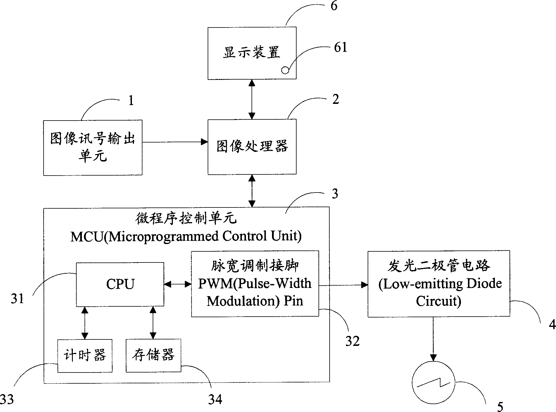
[0013] Such as figure 1 Shown is a structural schematic diagram of the intelligent LED control system of the present invention. The LED indicating device of the present invention is installed on the display equipment to indicate different working states of the display equipment. The LED indicating device drives the LED indicator light through different PWM waves to make it emit different brightness, thereby displaying different working states. To obtain different PWM waves, it is necessary to adjust the number of clock PWM unit cycles of the high level of the PWM wave. The PWM wave is composed of M PWM wave periods, and one PWM wave period has 255 PWM unit periods. The PWM unit period includes N clock periods. The numerical values ​​M and N are variables and can be determined according to specific needs. In this embodiment, the LED indicating device includes an image signal output unit 1, an image processor 2, a micro-programmable control unit (Micro-programmable Control U...


PUM


Abstract

This invention relates to an intelligent type LED controlling system, which comprises an image signal output unit, an image processor, a mini program controlling unit, a display device, a light-emitting diode circuit and a LED guiding light; wherein the mini program controlling unit comprises a CPU, a impulse-width modulation pin, a timer and a memory; said CPU is connected with the timer, memory and the impulse-width modulation pin, used for controlling each unit and generating PWM wave with some PWM cycle numbers according to the image signal condition; the timer is based on the clock cycle, and the memory will store the cycle number of the PWM wave and the controlling program. The invention also provides a controlling method of the intelligent type LED, which can prevent the disturbance to eyes.

Description

【Technical field】 [0001] The invention relates to a light-emitting diode (LED) based on an MCU microcontroller, in particular to a system and method for changing the brightness of an LED indicator light by using a pulse width modulation method (PWM). 【Background technique】 [0002] General electronic equipment, such as televisions, computers, etc., all use LEDs (Low Emitting Diode) as their working status indicators. The LED indicator light is used for the power state of the electronic equipment, such as the LED indicator light is on when the power is turned on, and the LED indicator light is off after the power is turned off. At present, there are mainly methods for controlling the brightness of LEDs: current control method, which changes the brightness by changing the current flowing through the LED. In this method, each pixel needs a controllable current source, and its disadvantage is that the circuit is complicated and the cost is high. PWM (Pulse-Width Modulation) is...

Claims


Application Information

Patent Timeline
Patent Type & Authority Applications(China)
IPC IPC(8): H05B37/02
CPCY02B20/42Y02B20/48Y02B20/40
Inventor 谢冠宏
Owner HONG FU JIN PRECISION IND (SHENZHEN) CO LTD
Why Eureka
Try Eureka