Collection/drainage plate

A drainage board and water-permeable technology, applied in soil protection, construction, infrastructure engineering, etc., can solve problems such as inability to collect and drain water, and achieve the effect of easy deformation

Inactive Publication Date: 2006-02-01
TOTAKU IND INC
View PDF0 Cites 5 Cited by
  • Summary
  • Abstract
  • Description
  • Claims
  • Application Information

AI Technical Summary

Problems solved by technology

[0008] However, in the case of drainage mats, the middle layer formed of many corrugated bands serves as a channel for the water absorbed from the thin plate-shaped member, but depending on the direction of water flow, the width and height of the corrugated bands become obstacles to water flow. , thus, high-efficiency water collection and drainage cannot be carried out, which is not considered in the above-mentioned prior art

Method used


Image

  • Collection/drainage plate
  • Collection/drainage plate
  • Collection/drainage plate

Examples


Embodiment

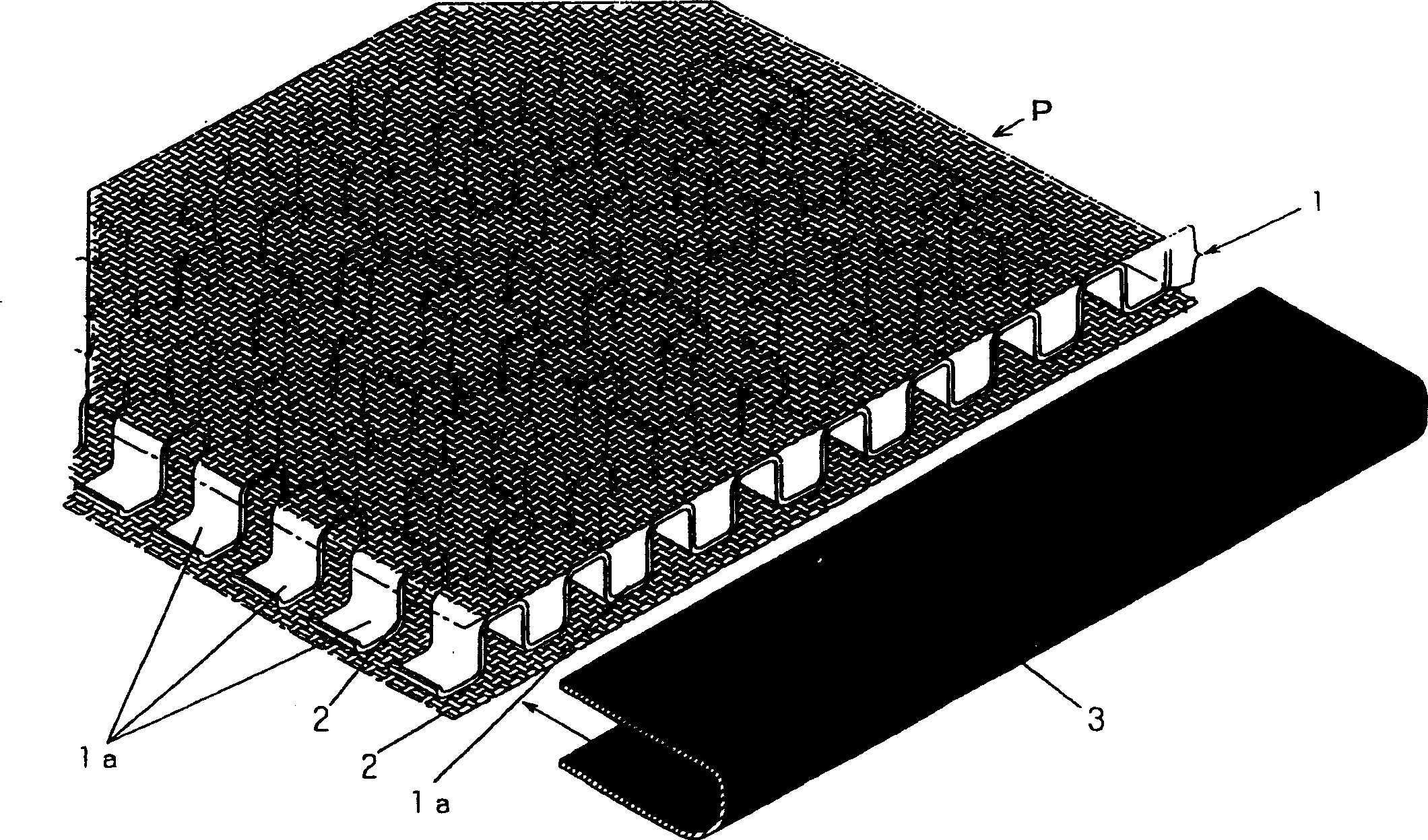
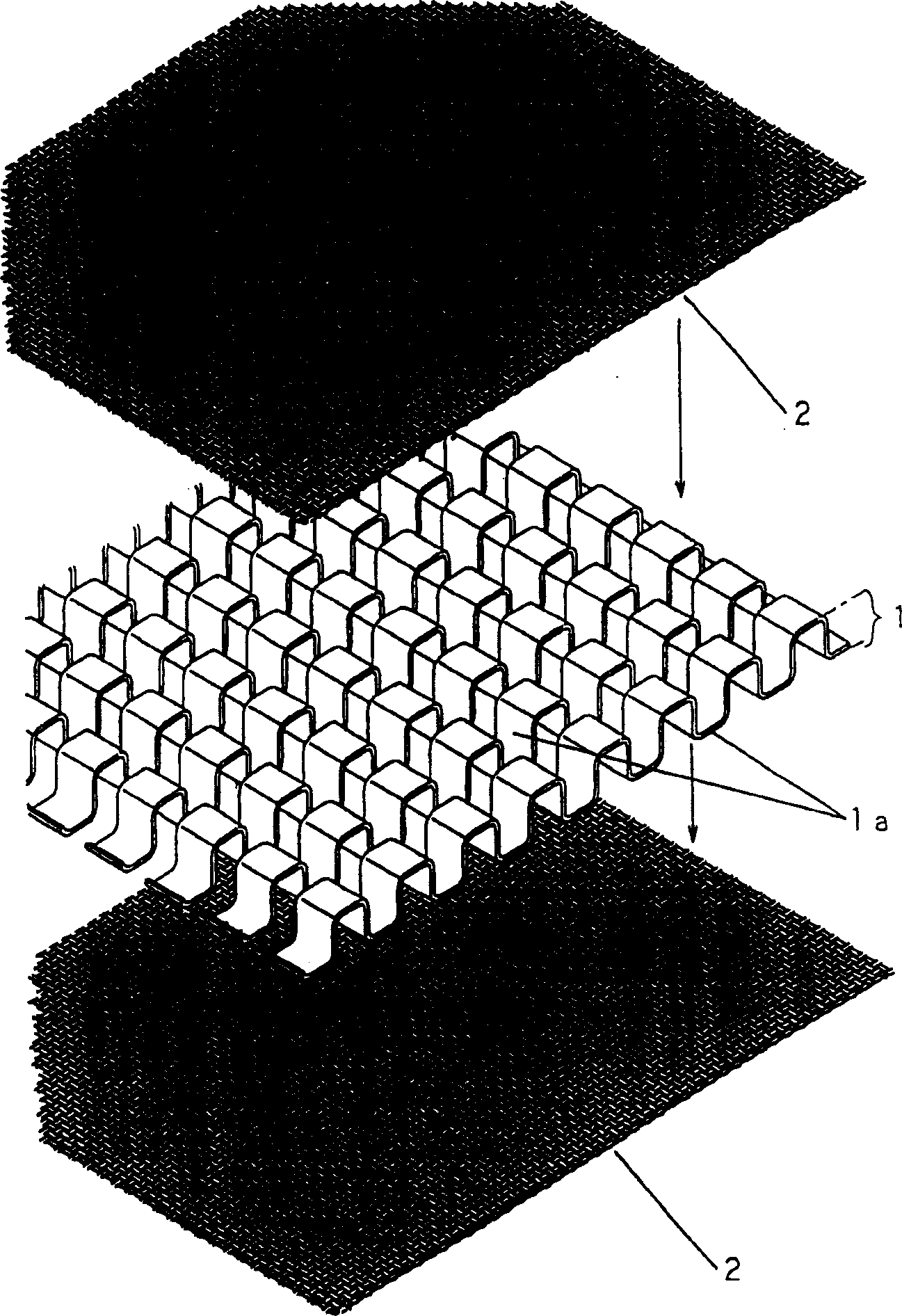
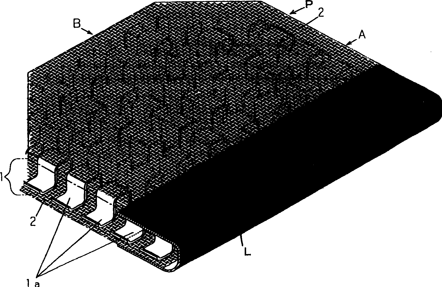
[0027] Hereinafter, embodiments of the present invention will be described together with illustrated examples, Figure 1 to Figure 8 It is a figure showing Example 1 of the present invention, figure 1 It is a perspective view after separating the water-impermeable sheet from the drainage plate, figure 2 It is an exploded perspective view of the middle layer of the drainage board and the permeable net, image 3 It is a three-dimensional view of the drainage board, Figure 4 is a partial front view of the collecting and draining plate, Figure 5 is from Figure 4The figure of the shape of the collection and drainage plate seen in the direction of A, Image 6 is from Figure 4 The figure of the shape of the collection and drainage plate seen in the direction of B, Figure 7 It is a diagram showing the state after laying the drainage board on the inclined surface, Figure 8 It is a figure which shows the arrangement|positioning state of a collection and drainage plate and ...


PUM


Abstract

The present invention provides a drain plate having an intermediate layer with excellent pressure resistance performance and having sufficient strength to endure an external impact or soil pressure and sufficiently holding a space as the intermediate layer and further guiding collected water securely and smoothly into a drain pipe by specifying the direction of a water flow and improving water-collecting and draining efficiency. A plate shaped body P comprises the intermediate layer 1 in which a plurality of portions of a wave form tape 1a made of a tape material of a synthetic resin with a predetermined width and formed into an almost U shaped uneven form in a side-view are arranged in parallel adjacently to one another at predetermined intervals, and water permeable nets 2, 2 which are arranged on both front and rear surfaces of the intermediate layer 1 and laminated on contact surfaces of each portion of the wave form tape 1a. A water impermeable sheet 3 covers the outer peripheral surface of the water permeable nets 2, 2 laminated thereon in a U shape in cross section to form a trough L at one side edge in parallel to the length direction of the wave form tape 1a.

Description

technical field [0001] The present invention mainly relates to a collection system that is installed underground in soft mud and water gushing grounds, and collects gushing water in the soil and seepage water caused by rainfall, etc., and discharges them into predetermined drainage pipes to stabilize the soil. Drainage panels, in more detail, refer to collection and drainage panels whose middle layer is formed by a number of corrugated strips. Background technique [0002] There are various reasons for the necessity of concentrating the water in the soil for drainage in this way: in sloped areas, in order to prevent the slope from collapsing like sandy soil; in agriculture, in order to dry the soil and avoid the accumulation of salt in the soil, Increase crop income; in road construction, in order to prevent the water in the lower layer of the road from softening the soil and causing the roadbed to sink, or to damage the road surface caused by freezing the roadbed to expand;...

Claims


Application Information

Patent Timeline
Patent Type & Authority Applications(China)
IPC IPC(8): E02D3/10
Inventor 平尾升司那波恒博
Owner TOTAKU IND INC
Why Eureka
Try Eureka