
Mining and driving method combined splitter with hydraulic breaking hammer

A technology of hydraulic breaker and splitter, which is applied in special mining, discharge machinery, earth drilling and mining, etc. It can solve problems such as inability to directly load vehicles, surrounding environmental pollution, dust flying, etc., and achieves wide application range, environmental protection, The effect of a good construction environment

Inactive Publication Date: 2006-02-01
惊天智能装备股份有限公司
View PDF0 Cites 12 Cited by
  • Summary
  • Abstract
  • Description
  • Claims
  • Application Information

AI Technical Summary

Problems solved by technology

[0002] Now the open-pit mining method usually first develops a mining face or steps on the vein, blasts or bursts the rock ore by drilling and blasting, and then uses a loader (mostly with an electric shovel) to load the rock ore out of the stope. [For details, see "Open Pit Mining of Metal Ore Deposits" edited by Li Baoxiang, etc., published by Metallurgical Industry Press] Sometimes large pieces of ore will be produced after blasting, which cannot be loaded directly, and need to be crushed for the second time before loading. Flying sand and rocks, flying dust, strong vibration and impact, and can release harmful gases, causing hidden dangers to the safety of people and buildings, and polluting the surrounding environment; some are not allowed to use blasting due to geological conditions, geographical location and other reasons. legal mining

Method used


Image

  • Mining and driving method combined splitter with hydraulic breaking hammer
  • Mining and driving method combined splitter with hydraulic breaking hammer
  • Mining and driving method combined splitter with hydraulic breaking hammer

Examples


Embodiment 1

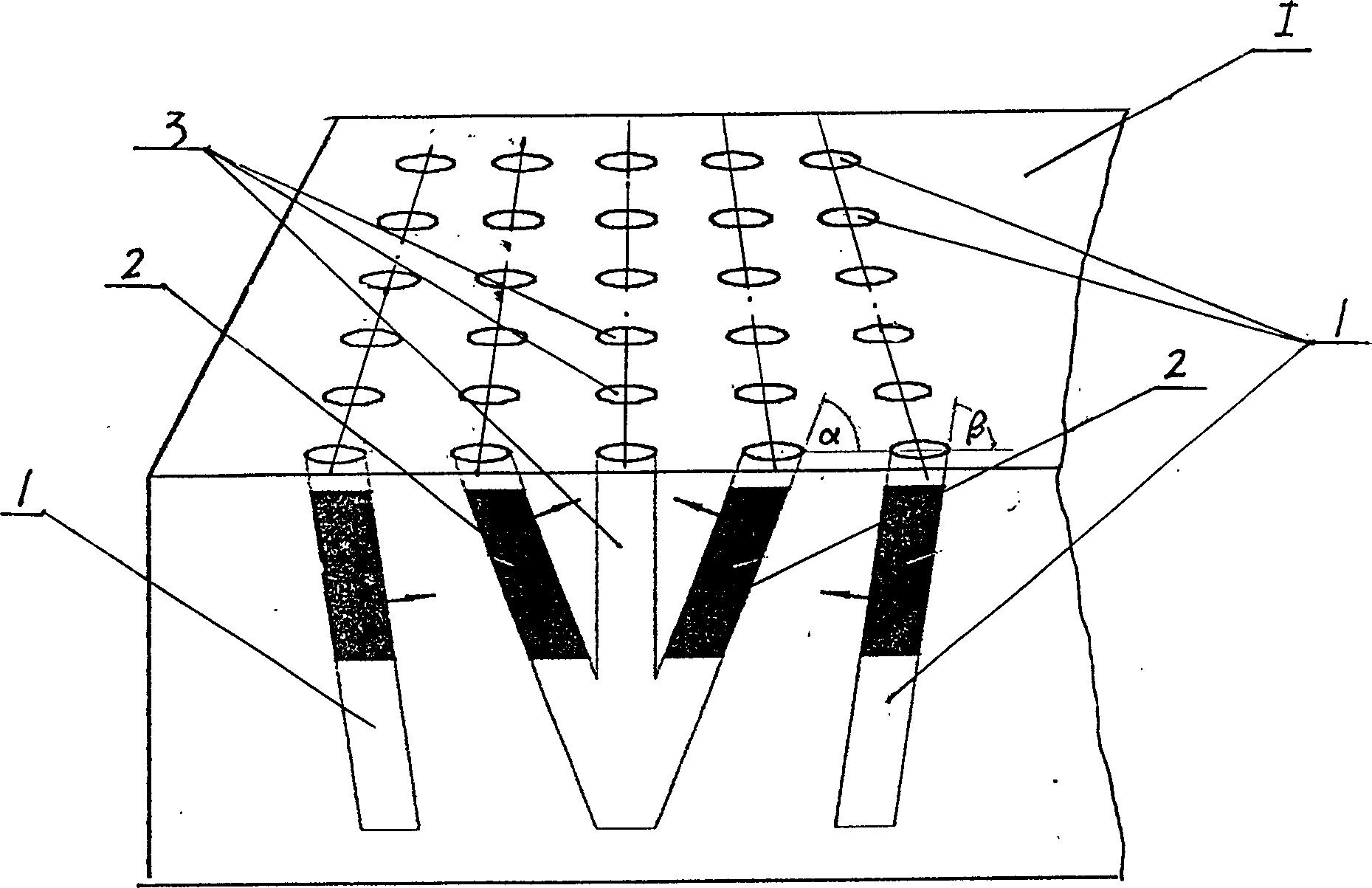
[0022] In a joint mining test in a mine, on the horizontal working face of the rock ore body, a drilling machine was used to drill 5 rows of 25 holes in total, including 5 cut holes in the middle, and the inner split holes on the left and right sides respectively. 5, 5 outer split holes on the left and right sides respectively, the measured hole depths are 805mm, 860mm and 998mm, the hole diameters are 70mm, 125mm and 200mm, the hole distance is 800mm, the center of each left inner split hole The angle between the line and the rock plane is 30°, the angle between the center line of each right inner split hole and the rock plane is 45°, and the angle between the center line of each left outer split hole and the rock plane is 50° °, the angle between the center line of the outer split hole on the right side and the rock plane is 80°, and a splitter is placed in each inner and outer split hole, and the plungers of the splitter are all pointed to the cut hole, and then the Through...

Embodiment 2

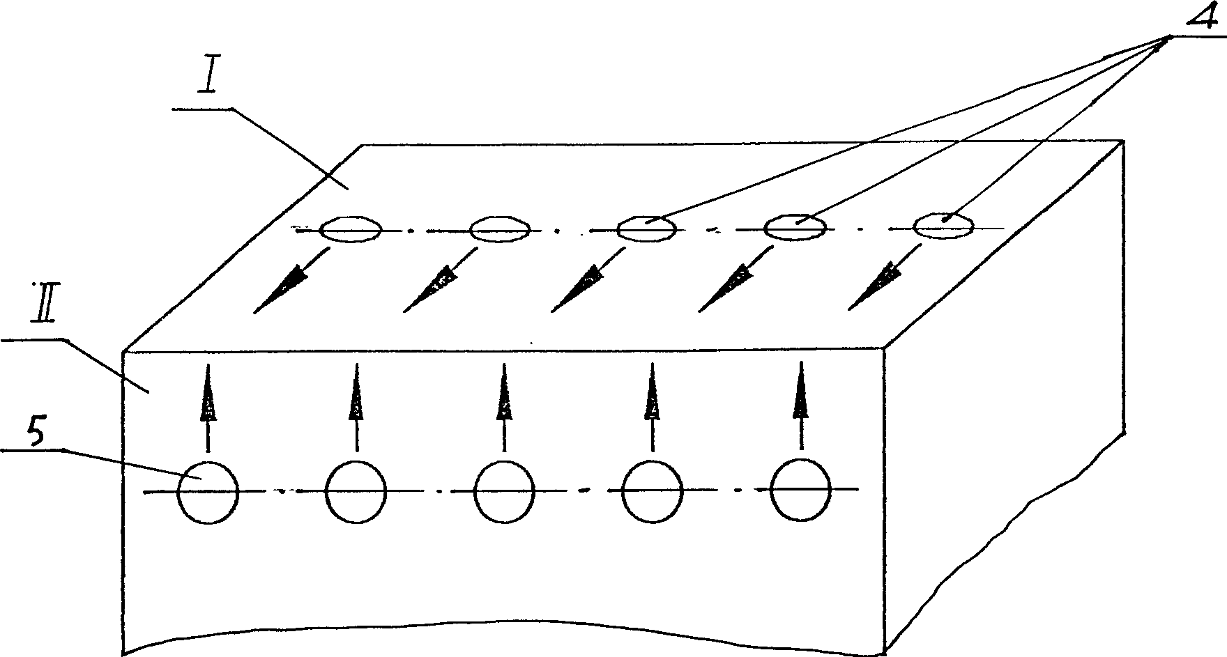
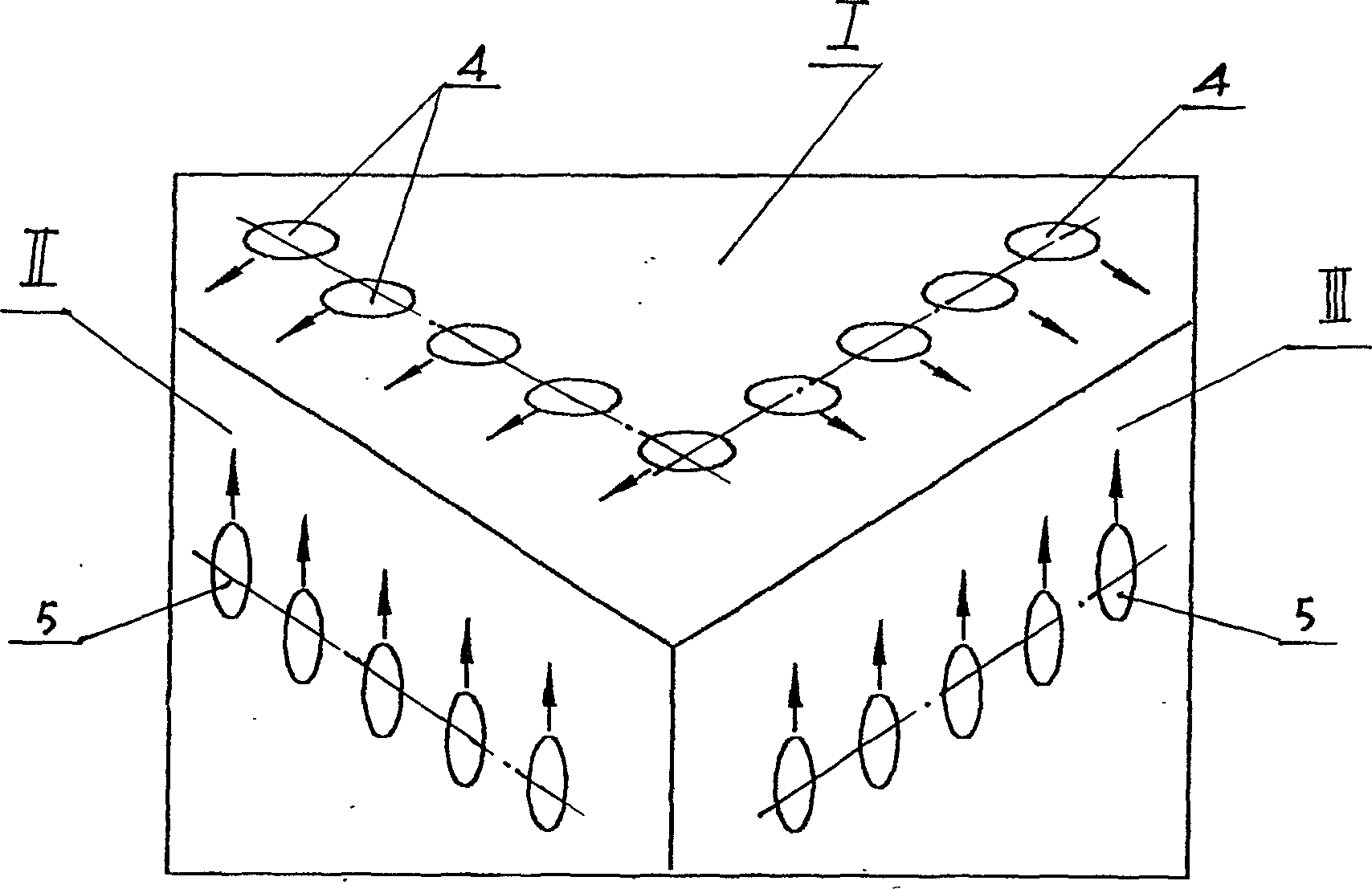
[0024] In a joint mining test in a mine, on a vertical working surface with a horizontal working surface and two adjacent vertical working surfaces that are approximately at right angles to each other, first use a drilling machine to drill a right-angled hole on the horizontal working surface with a depth of 805mm. , the hole diameter is 120mm, the hole distance is 800mm and the hole depth is 1000mm, the hole diameter is 65mm, and the hole distance is 800mm. There are 5 horizontal holes with a drilling depth of 810mm, a hole diameter of 70mm, 105mm, and 200mm, and a hole spacing of 800mm. A splitter is placed in each vertical hole and horizontal hole, and the splitter placed in the vertical hole The plunger points to the corresponding vertical working surface, the plunger of the splitter placed in the horizontal hole points to the corresponding horizontal working surface, the peripheral oil source is connected, each splitter works, and the rock mass is split within 4-5 minutes ...


PUM

PropertyMeasurementUnit
Hole depthaaaaaaaaaa
Apertureaaaaaaaaaa

Abstract

A mining method combining rock splitting machine with hydraulic breaking hammer features that the rock-splitting machine, hydraulic rock-breaking hammer, drilling machine and loading machine are used. Its technology includes such steps as drilling holes, installing the splitting machine in each hole, splitting rock, breaking rock by hydraulic rock-breaking hammer, and transporting the broken rock by loading machine. Its advantages are no strong vibration, and no environmental pollution.

Description

technical field [0001] The invention belongs to mining and driving, in particular to a method for mining in an open-pit mine and driving in a rock roadway. Background technique [0002] Now the open-pit mining method usually first develops a mining face or steps on the vein, blasts or bursts the rock ore by drilling and blasting, and then uses a loader (mostly with an electric shovel) to load the rock ore out of the stope. [For details, see "Open Pit Mining of Metal Ore Deposits" edited by Li Baoxiang, etc., published by Metallurgical Industry Press] Sometimes large pieces of ore will be produced after blasting, which cannot be loaded directly, and need to be crushed for the second time before loading. Flying sand and rocks, flying dust, strong vibration and impact, and can release harmful gases, causing hidden dangers to the safety of people and buildings, and polluting the surrounding environment; some are not allowed to use blasting due to geological conditions, geographi...

Claims


Application Information

Patent Timeline
IPC IPC(8): E21C47/10E21C37/00
Inventor 郝其昌罗铭
Owner 惊天智能装备股份有限公司
Learn More