
Micro manipulator used for throat surgery

A micro-manipulator, surgical technology, applied in the direction of micro-manipulator, manipulator, surgery, etc., to achieve the effect of easy coordination of interference and reduction of radial size

Inactive Publication Date: 2006-02-08
TIANJIN UNIV
View PDF1 Cites 10 Cited by
  • Summary
  • Abstract
  • Description
  • Claims
  • Application Information

AI Technical Summary

Problems solved by technology

So far, there is no micromanipulator for throat surgery in China

Method used


Image

  • Micro manipulator used for throat surgery
  • Micro manipulator used for throat surgery

Examples


Embodiment Construction

[0013] A micromanipulator for throat surgery of the present invention will be described in further detail below in conjunction with the accompanying drawings and specific embodiments.

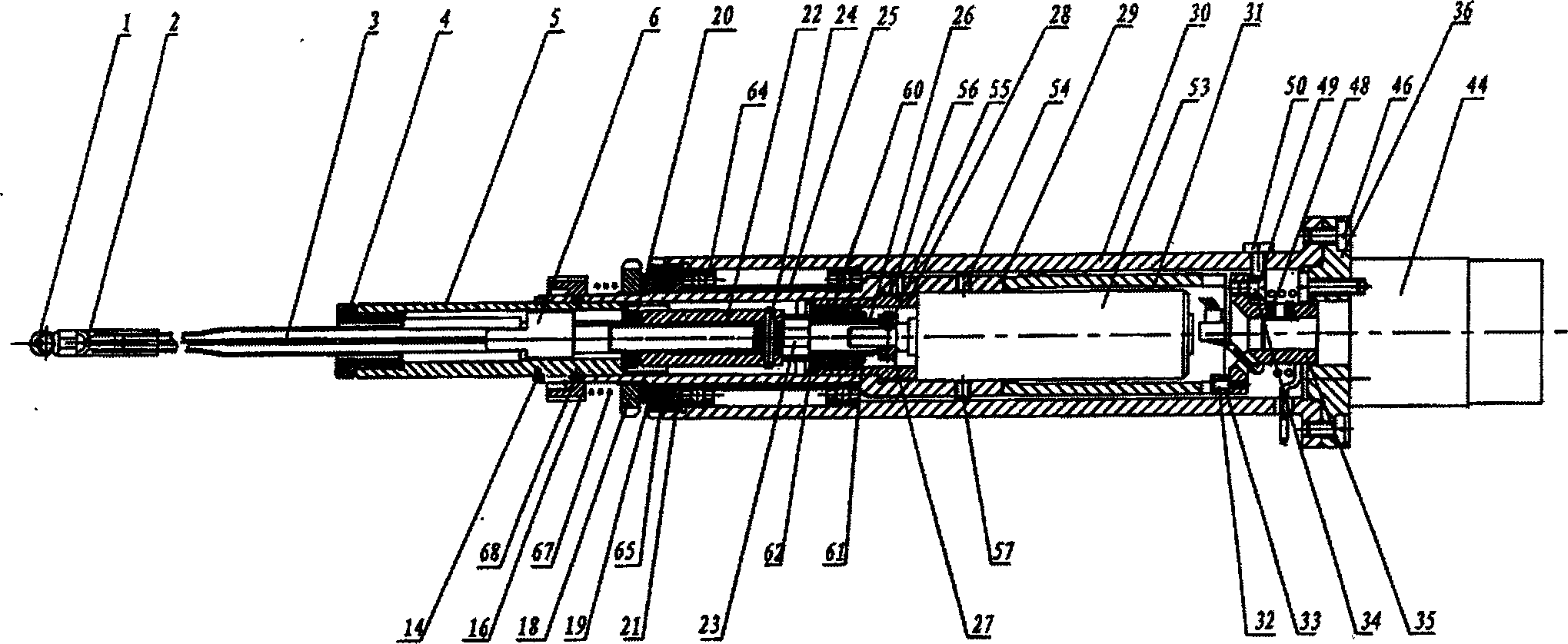
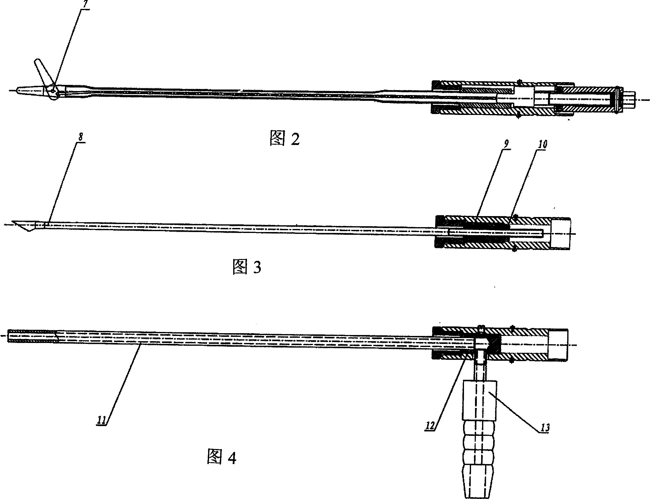
[0014] Such as figure 1 As shown, a micromanipulator for throat surgery of the present invention includes a body 30, a fingertip instrument mechanism, an instrument replacement mechanism, an instrument rotation mechanism, an instrument opening and closing mechanism, and an instrument limiting mechanism; the body 30 adopts a sleeve structure; The fingertip instrument mechanism includes a fingertip part and a support tube 5; one end of the support tube 5 of the fingertip instrument mechanism is arranged in the hole at the front end of the body 30 sleeve; the instrument dismounting mechanism adopts a steel ball chuck structure, which includes a plurality of steel balls 68, an operating ring 16, a transmission sleeve 29 and a spring 67, and the front end surface of the transmission sleeve 29 is pro...


PUM


Abstract

The invention discloses a micro manipulator for throat operation, which comprises a body a finger tip mechanical mechanism, a remove mechanism, a rotation mechanism, a switch mechanism, and a limit mechanism. Compared with existing technique, this invention has benefit as: 1. the series-type envelope distribution can decrease finger radial size fit to narrow space; 2. the approximate crank rocker mechanism, which composes of a throat clamp, a pin, a drive steel wire and a screw, can transfer motion precisely and obtain required stretch angle.

Description

technical field [0001] The invention relates to a medical device, in particular to a component of the medical device used in laryngeal surgery. Background technique [0002] Chinese invention patent 03100038.x discloses "a micromanipulator for microsurgery", which includes a body, a fingertip instrument mechanism, an instrument replacement mechanism, an instrument rotation mechanism, an instrument opening and closing mechanism, and an instrument limit mechanism, but At present, this mechanism is only used in microsurgery, and cannot fully meet the operation requirements of laryngeal surgery. The existing foreign surgical micromechanical fingers mainly use piezoelectric drive and memory alloy drive. The opening angle of the finger is relatively small in the way of piezoelectric drive, and the force generated is relatively small. If a relatively large force is to be generated, the volume and weight will be large. The response of the micro-mech...

Claims


Application Information

Patent Timeline
IPC IPC(8): B25J7/00A61B17/24
Inventor 王树新李群智周永春丁杰男邱波
Owner TIANJIN UNIV
Learn More