Pressure device of molding press and pressuring method thereof
A technology of pressurizing device and molding machine, which is applied in the field of pressurizing device, can solve the problems of low efficiency and laborious processing, etc., and achieve the effect of high efficiency, convenient use and fast speed
- Summary
- Abstract
- Description
- Claims
- Application Information
AI Technical Summary
Problems solved by technology
Method used
Image

Examples
Embodiment 1
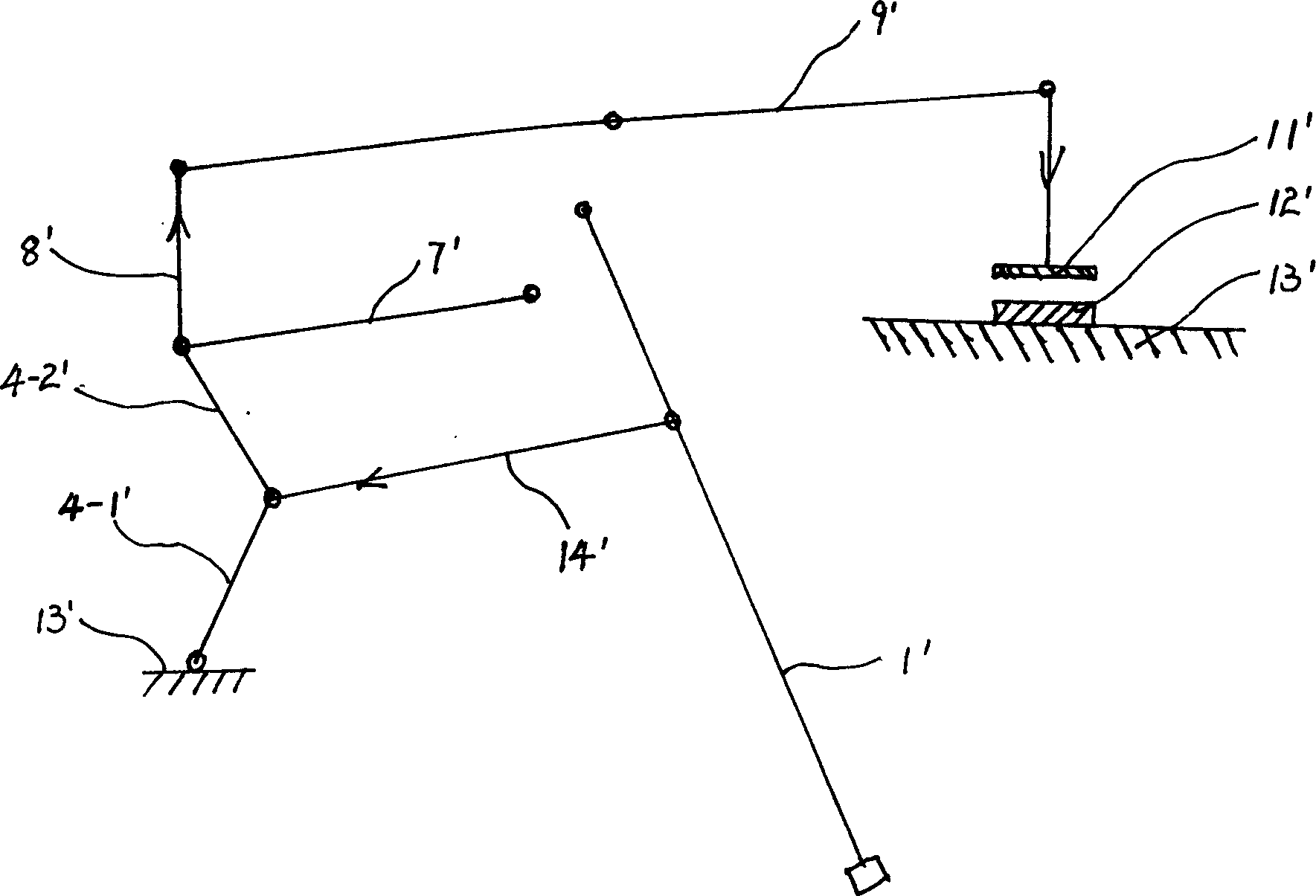
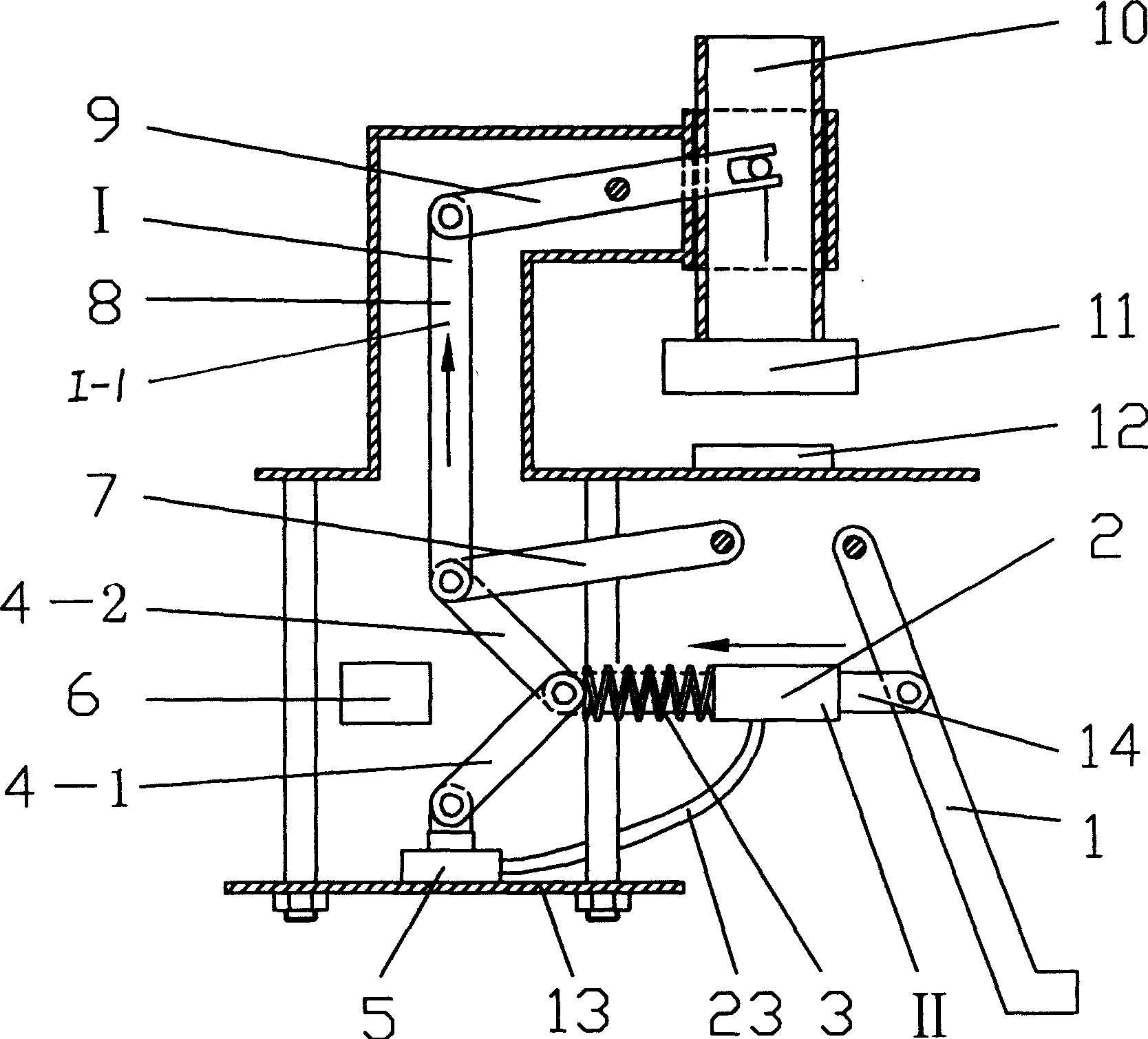
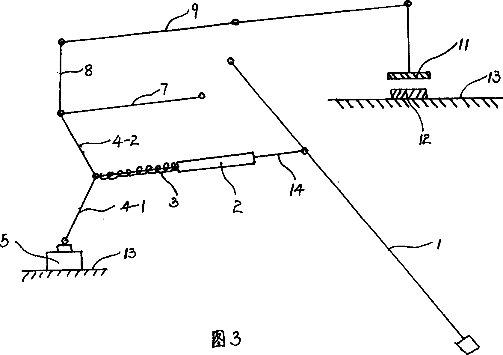
[0025] see figure 2 , this embodiment includes a frame 13, a mechanical transmission mechanism I and a pressurization mechanism II, and the mechanical transmission mechanism I, the pressurization mechanism II and the mold 11 are connected in series.
[0026] The mechanical transmission mechanism I is a toggle link mechanism, which is composed of a slider 10, a connecting rod structure I-1, and a pedal rod 1, wherein the connecting rod structure I-1 includes a cross bar 9, a straight bar 8, and a pull bar 7 , upper connecting rod 4-2, lower connecting rod 4-1, pressurizing mechanism II is hydraulic mechanism, is made up of main oil cylinder 5, auxiliary oil cylinder 2, spring 3, connecting rod 14, wherein main oil cylinder 5 is fixed on the frame 13 , the mold 11 is fixed below the slide block 10, one end of the cross bar 9 is connected with the slide block, and the other end is movably connected with the straight bar 8, the upper connecting rod 4-2, the lower connecting rod 4...
Embodiment 2
[0029] The difference between the present embodiment and embodiment 1 is that the position of the auxiliary oil cylinder 2 is as shown in Figure 5, that is, between the mechanical transmission mechanism 1 and the auxiliary oil cylinder 2, connecting rods 15, 16 are added; its method of use is the same as in embodiment 1, The state after stepping on the pedal lever 1 is as follows Figure 6 As shown, due to the increase of the connecting rods 15 and 16, when the pressurization stroke is completed, the reaction force of the auxiliary oil cylinder 2 acting on the pedal rod 1 can be reduced, increasing the comfort of operation.
Embodiment 3
[0031] Referring to Fig. 7, the difference between this embodiment and Embodiment 1 is that the main oil cylinder 5 is connected with the oil pump 22, that is, the main oil cylinder 5 is supplied with oil by the oil pump 22, and the shaft of the pedal rod 1 directly passes through the connecting rod 14 and the lower connecting rod. 4-1 is connected to the junction of the upper connecting rod 4-2, and the auxiliary cylinder 2 and the spring 3 are omitted; -2 and the lower connecting rod 4-1 extend to the self-locking position to complete the mold clamping stroke, then connect the oil pump 22, and the main oil cylinder 5 is supplied with oil by the oil pump 22 to generate a thrust to act on the workpiece 12 to complete the pressurization stroke.
[0032] The master cylinder 5 in this embodiment can also be supplied with oil by devices such as a hydraulic station.
PUM
 Abstract
Description
Claims
Application Information
 - Generate Ideas
- Intellectual Property
- Life Sciences
- Materials
- Tech Scout
- Unparalleled Data Quality
- Higher Quality Content
- 60% Fewer Hallucinations
Browse by: Latest US Patents, China's latest patents, Technical Efficacy Thesaurus, Application Domain, Technology Topic, Popular Technical Reports.
© 2025 PatSnap. All rights reserved.Legal|Privacy policy|Modern Slavery Act Transparency Statement|Sitemap|About US| Contact US: help@patsnap.com