Permanent magnet biased external rotor radial magnetic bearing

A permanent magnetic bias, external rotor technology, applied in the direction of magnetic bearings, bearings, shafts and bearings, etc., can solve the problems of large excitation current, increased bearing power consumption, long axial length, etc., to reduce copper consumption and control power amplifiers Effects of loss, elimination of bias current, and reduction of axial size

Inactive Publication Date: 2006-02-08
BEIHANG UNIV
View PDF0 Cites 21 Cited by
  • Summary
  • Abstract
  • Description
  • Claims
  • Application Information

AI Technical Summary

Problems solved by technology

However, some of the current permanent magnet bias outer rotor radial magnetic bearing structures are based on ordinary radial electromagnetic bearings, and permanent magnets are placed upward on the electromagnetic magnetic circuit, so that the magnetic flux generated by the control coil must pass through the permanent magnets. Due to the large reluctance of the permanent magnet, a large excitation current is required for the control coil to generate a certain electromagnetic flux, which will obviously increase the power consumption of the bearing; some structures directly connect the permanent magnet to the stator laminated core, so that the permanent magnet When the magnetic circuit passes through the stator core vertically, it will lose too much magnetomotive force, which will greatly weaken the attraction forc

Method used


Image

  • Permanent magnet biased external rotor radial magnetic bearing

Examples


Embodiment Construction

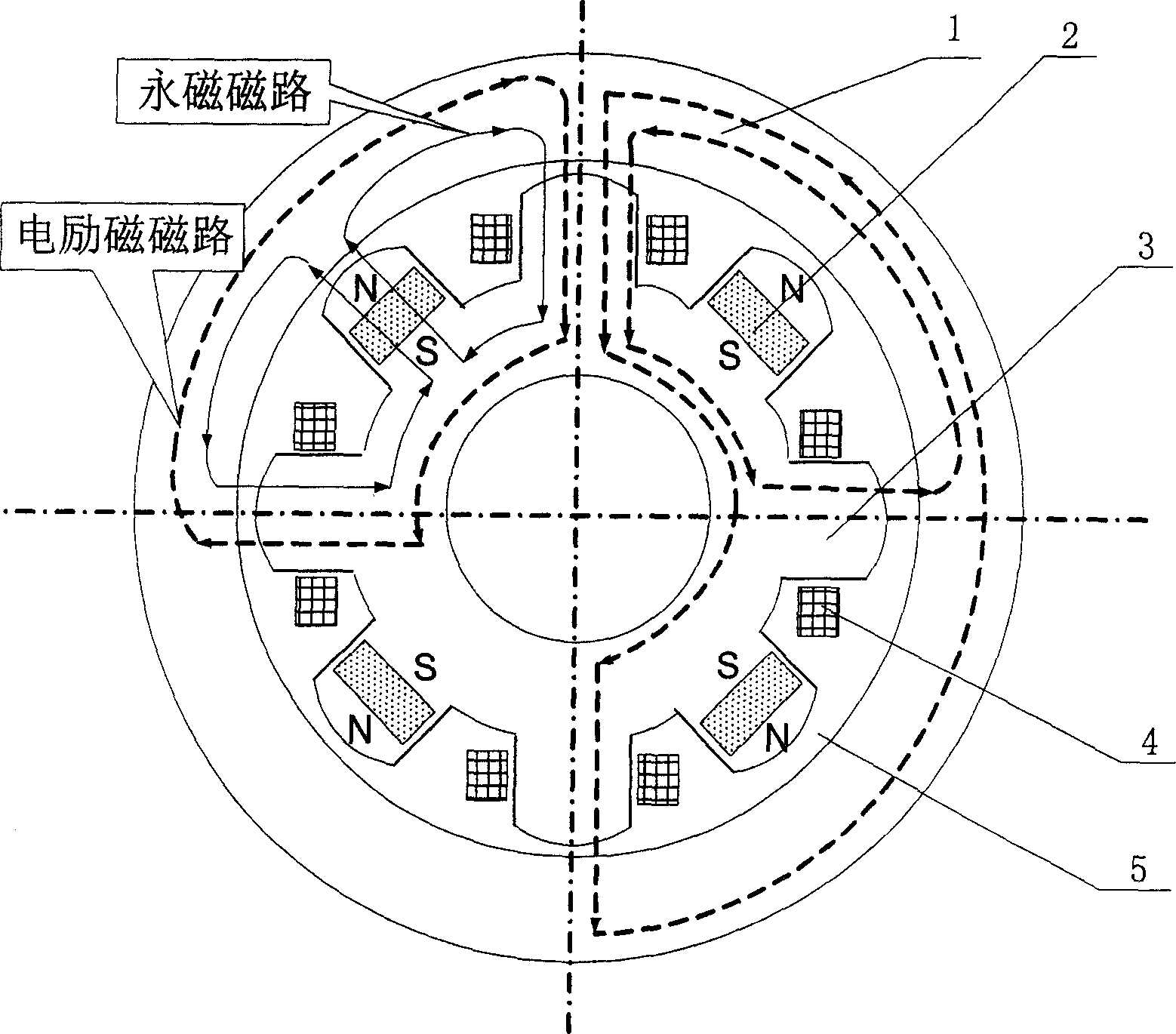
[0008] like figure 1 As shown, the present invention is composed of a rotor core 1, a permanent magnet 2, a stator core 3, and an excitation coil 4. The magnetic poles of 8 stator cores 3 are evenly distributed on the circumference of the magnetic bearing, and 4 permanent magnets 2 are embedded in the stator core at intervals. Among the four magnetic poles of 3, that is, the two sides of the stator core pole embedded with the permanent magnet 2 are the stator core poles not embedded with the permanent magnet 2. And the four magnetic poles of the stator core 3 not embedded in the permanent magnet 2 are distributed along +X, -X, +Y and -Y, and are surrounded by exciting coils. For the convenience of processing and installation, and considering the factor of magnetic saturation, the distance between the two ends of the stator core 3 and the two ends of the permanent magnet 2 embedded in it is about 0.5mm; there is a certain gap between the outer surface of the stator core 3 and t...


PUM


Abstract

The permanent magnetic offset external rotor magnetic radial bearing consists of rotor iron core, permanent magnet, stator iron core, exciting winding and air gap. Eight stator iron core magnetic poles are distributed homogeneously in a circumference; four permanent magnets are embedded separately inside the stator iron core magnetic poles in the angle of 90 deg; and the four stator iron core magnetic poles without embedded permanent magnet are distributed separately in the +X, -X, +Y and -Y directions wound with exciting winding. Between the outer surface of the stator iron core and the inner surface of the rotor iron core, there is air gap. The permanent magnets form the offset magnetic fields in both X direction and Y direction via adjacent stator iron core magnetic poles. Compared with available permanent magnetic offset external rotor magnetic radial bearing, the present invention has the advantages of small size, low power consumption, reliable performance and easy control.

Description

Technical field [0001] The invention relates to a non-contact magnetic suspension bearing, in particular to a small-volume, low-power-consumption permanent-magnet-biased outer-rotor radial magnetic bearing, which can be used as non-contact support for rotating parts in spacecraft such as satellites and space stations. Background technique [0002] Magnetic suspension bearings are divided into pure electromagnetic bearings and hybrid magnetic suspension bearings with permanent magnetic bias and electromagnetic control. The former uses large current and consumes a lot of power, and the hybrid magnetic suspension bearings with permanent magnetic bias and electromagnetic control. The magnetic field generated by the permanent magnet bears the main load. Bearing capacity, the electromagnetic field provides auxiliary adjustment bearing capacity, so this kind of bearing can greatly reduce the control current and reduce the loss. However, some of the current permanent magnet bias out...

Claims


Application Information

Patent Timeline
IPC IPC(8): F16C32/04
CPCF16C32/048F16C32/0465F16C2300/20
Inventor 孙津济房建成韩邦成
Owner BEIHANG UNIV
Why Eureka
Try Eureka