Vortex compressor

A technology of scroll compressors and moving scrolls, applied in the field of scroll compressors, can solve the problems of unstable working conditions, limited use occasions, and shortened service life of compressors, and achieve compact structure, increased stability, and reduced power consumption. consumption effect

Inactive Publication Date: 2006-02-15
LANZHOU UNIVERSITY OF TECHNOLOGY
View PDF0 Cites 7 Cited by
  • Summary
  • Abstract
  • Description
  • Claims
  • Application Information

AI Technical Summary

Problems solved by technology

In the usual scroll compressor structure, each friction pair is lubricated by oil injection, and the movable scroll drive bearing is placed outside the movable scroll disc. This structure is due to the difference between the gas force acting plane and the moving scroll centrifugal force acting plane. The driving planes of the movable scroll are not coplanar, resulting in an overturning moment against the movable scroll, resulting in unstable working conditions of the compressor and shortened service life, and oil is contained in the oil-lubricated compression medium, which limits its use.

Method used


Image

  • Vortex compressor
  • Vortex compressor

Examples


Embodiment Construction

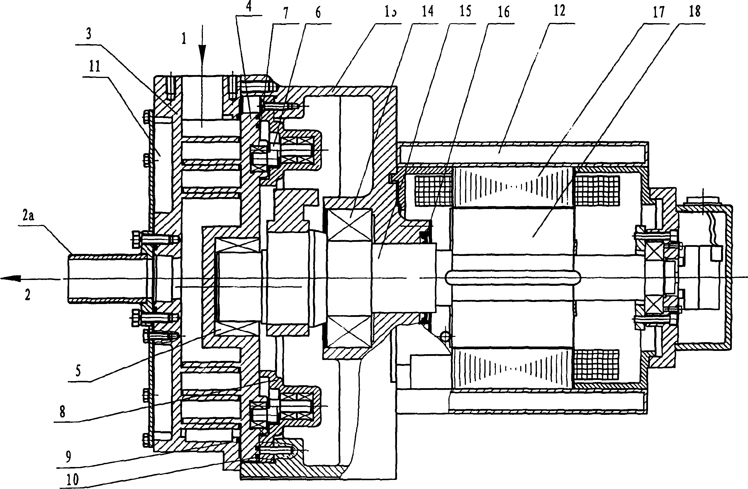
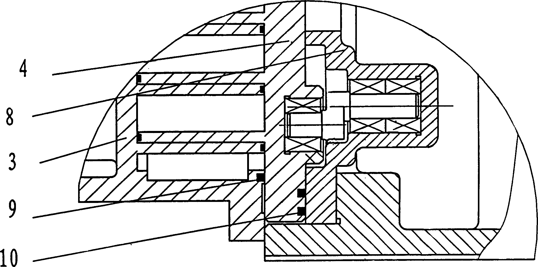
[0008] Such as figure 1 , figure 2 As shown, the compressed medium is inhaled through the suction port (1), and discharged through the exhaust port (2) after being compressed. The crankshaft (15) is installed on the support body (13) through the bearing (14), and the motor stator (17) Connected with the support body (13), the motor rotor (18) is directly installed on the crankshaft (15), driving the movable scroll (4) to perform rotary and translational motions, and the scroll teeth on the movable scroll (4) are in contact with the static The scroll teeth on the scroll (3) are staggered and meshed to form a closed compression chamber, which is composed of an orbiting scroll (4), a small bell crank (6), a bearing (7) and a support insert (8) to prevent rotation Mechanism, the upper end of the small crank throw (6) is embedded in the end plate of the movable scroll (4) through the bearing (7), the lower end is installed in the supporting embedded iron (8), and the supporting e...


PUM


Abstract

This invention relates a whirlpool compressor, which is to realize the none-oil lubricating of the compressor and reduce the tipping toque on the stirring whirlpool plate produced from the gas power and the centrifugal inertia force, and increases the working stability of the compressor, and prolongs the life the driving bearing. The defending self-rotating structure is composed of the stirring whirlpool plate (4), the small wrist joint (6), the bearing (7), and the bearing embedded clamp (8), wherein the top of the small wrist joint (6) is embedded at the end plate of the stirring whirlpool plate (4) through the bearing (7), and the under part of the small wrist joint (6) is mounted in the bearing embedded clamp (8), and he bearing embedded clamp (8) is mounted on the frame. The driving bearing (5) is embedded in the central part of the stirring whirlpool plate. Wherein the self-lubricating material (10) is arranged on the whirlpool plate surface that connects with the stirring whirlpool plate (4) and the bearing embedded clamp (8), and the self-lubricating material (9) is arranged on the connecting surface of the static whirlpool plate (3) and the stirring whirlpool plate (4).

Description

technical field [0001] The invention relates to a scroll compressor in a fluid displacement machine. Background technique [0002] The main components of the scroll compressor are: movable scroll, fixed scroll, bracket body, crankshaft, motor, etc. The profiles of the movable and static scrolls are exactly the same, and the phases are eccentrically arranged by 180°. The movable and static scrolls are meshed to form a closed compression chamber, and the medium is gradually compressed from the outside to the inside to realize suction, compression and exhaust. In the usual scroll compressor structure, each friction pair is lubricated by oil injection, and the movable scroll drive bearing is placed outside the movable scroll disc. This structure is due to the difference between the gas force acting plane and the moving scroll centrifugal force acting plane. The driving planes of the movable scroll are not coplanar, resulting in an overturning moment to the movable scroll, resul...

Claims


Application Information

Patent Timeline
Patent Type & Authority Applications(China)
IPC IPC(8): F04C29/02F04C18/02
Inventor 李超刘振全赵荣珍赵嫚彭斌刘兴旺王君杜桂荣陈胜
Owner LANZHOU UNIVERSITY OF TECHNOLOGY
Why Eureka
Try Eureka