Light guide plate with analogous triangular prism structure

A triangular prism and light guide plate technology, applied in prism, optics, nonlinear optics, etc., can solve the problems of panel waste, cost reduction, light energy loss, etc. of liquid crystal displays, and achieve brightness improvement, manufacturing cost reduction, cost control Effect

A triangular prism and light guide plate technology, applied in prism, optics, nonlinear optics, etc., can solve the problems of panel waste, cost reduction, light energy loss, etc. of liquid crystal displays, and achieve brightness improvement, manufacturing cost reduction, cost control Effect

CN1734324AInactive Publication Date: 2006-02-15ACE T

Image

  • Light guide plate with analogous triangular prism structure
  • Light guide plate with analogous triangular prism structure
  • Light guide plate with analogous triangular prism structure

Examples


Embodiment Construction

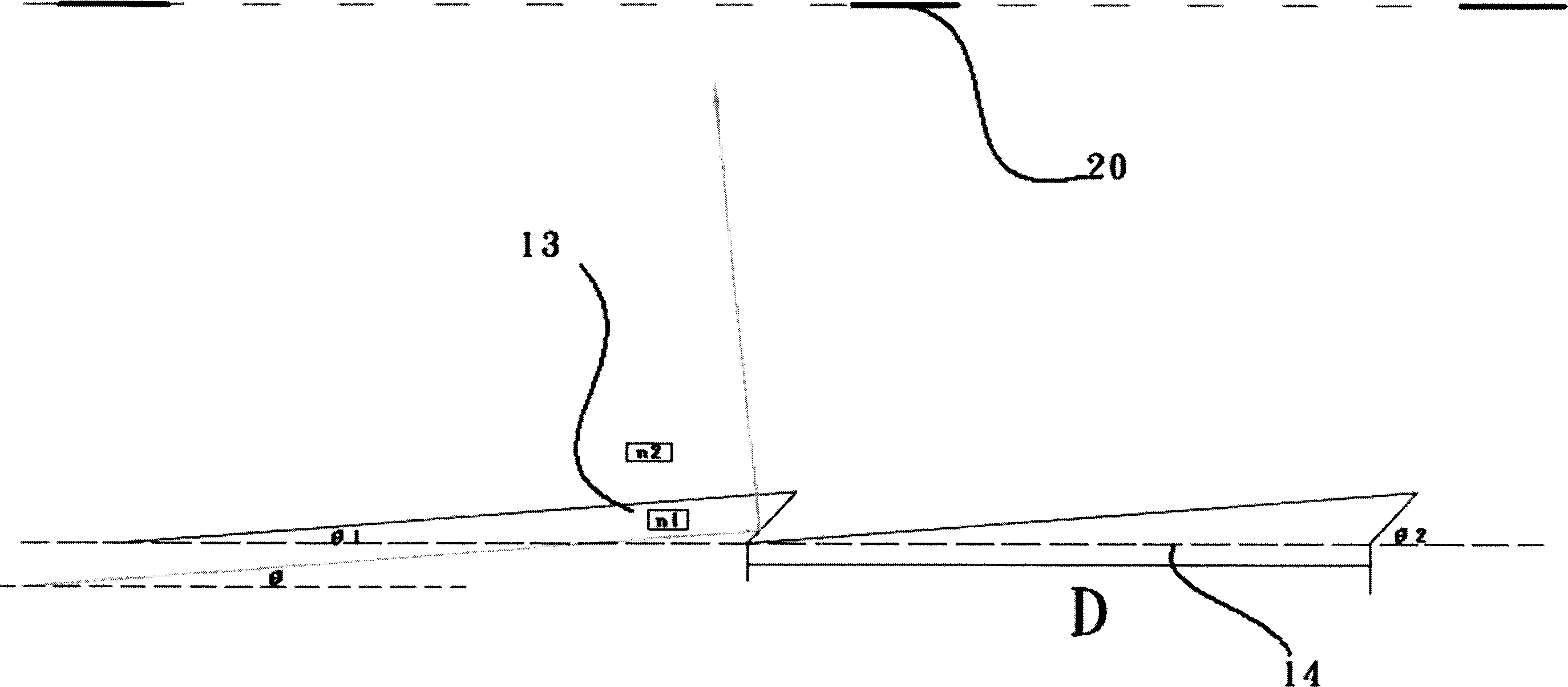
[0055] The present invention is a light guide plate with triangular prism structure, such as figure 1 As shown, the arrangement of the quasi-triangular prisms 13 is a neatly arranged obtuse triangle, wherein D is the width of the bottom surface 14 of the quasi-triangular prism, and the width of the quasi-triangular prism bottom just corresponds to the distance from the opening 20 of the panel of the liquid crystal display, so that the light passes through The light emitted by the total reflection inside the quasi-triangular prism 13 just corresponds to the opening 20 of the panel of the liquid crystal display, so that the light energy is effectively used, the brightness can be improved, and the picture quality of the liquid crystal display can be improved.

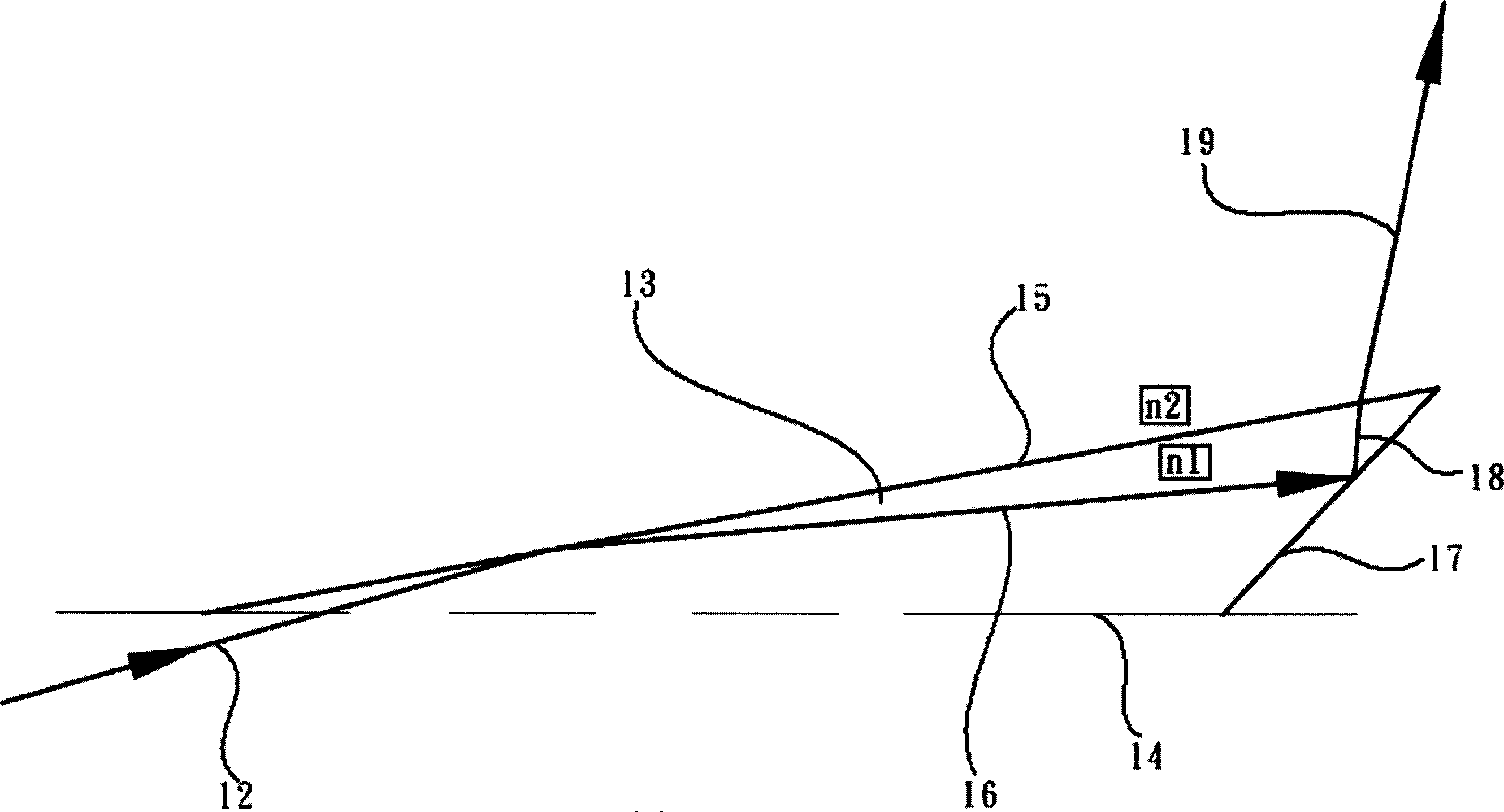
[0056] cooperate again figure 2 and Figure 6-1 As shown, it is one of various light angles entering it, wherein the light is injected into the light guide plate 11 by the light source 10, and then the incident light 12...


PUM


Abstract

The invention relates to a triangle prismatic optic platform, which adapts common or parallel illuminating source to shine optical surface of the optic platform. Each optical outlet position of exit optical beam reflects or refracts totally through triangle prismatic optic platform special separation angle. The distance of exit optical beam centre-line equals to or is less than the distance of LCD display platform adjacent opening. Complex parallel exits vertical optical line of optic platform by controlling complex specific position. The common illuminating source directs light to triangle prism through the LCD opening. The optical energy is catched and exited most of the entire reflection within the optic platform repeatedly.

Description

[0001] technical field [0002] The light guide plate with a triangular prism-like structure of the present invention is related to the use of prism sheets, diffusion plates, reflectors and other optically effective diaphragms in order to overcome the conventional backlight module. Most of the energy is lost in the process of repeated refraction and re-reflection, and there is a problem of being wasted due to the problem of irradiating the opaque part of the LCD panel, creating a non-comprehensive and selected complex Light is emitted from a specific position, and the light beams can also be formed at a concentrated azimuth angle by the cooperation of a plurality of controlled parallel lights, and the backlight module is emitted to the opening of the panel of the liquid crystal display, and the present invention is complicated to integrate the conventional multi-chip backlight module structure, directing the invention into simplified modules. Background technique [0003] Mo...

Claims


Application Information

Patent Timeline
15 Feb 2006
Publication
CN1734324A
IPC
G02F1/1335; G02B5/04
Inventors
宫下; 和博