Lighting device and image display unit and light guide provided with it
A lighting device and light guide technology, which is applied to the image display device and light guide body equipped with the device, the image display device and light guide body, and the field of lighting devices. Display quality degradation and other issues
- Summary
- Abstract
- Description
- Claims
- Application Information
AI Technical Summary
Problems solved by technology
Method used
Image
Examples
no. 1 Embodiment approach
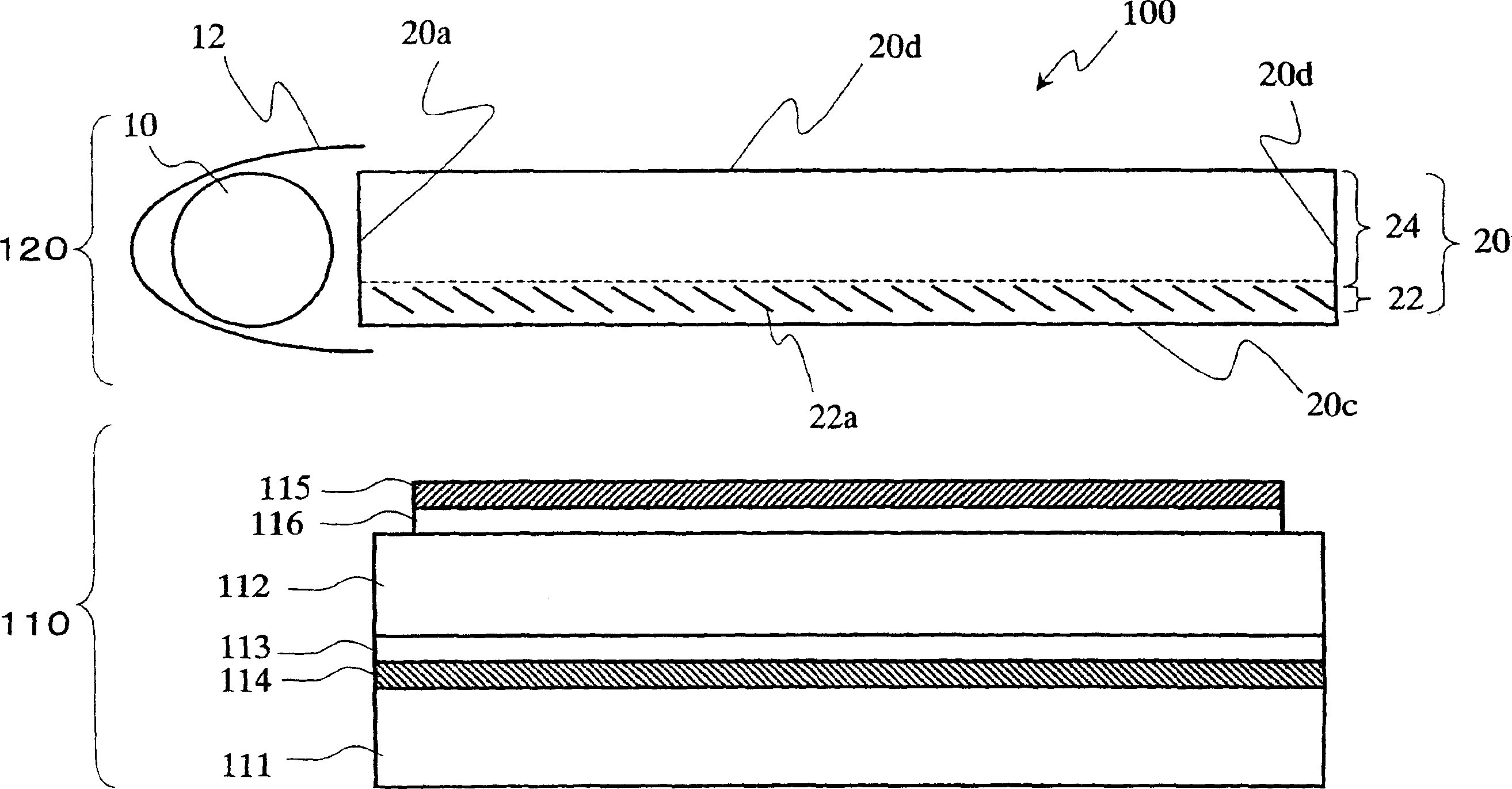
[0152] First, refer to figure 1 The configuration of the lighting device 120 according to the embodiment of the present invention and the liquid crystal display device (image display device) 100 including the lighting device 120 will be described.
[0153] Such as figure 1 As shown, the liquid crystal display device 100 is a reflective liquid crystal display device including a reflective liquid crystal display panel 110 and an illuminating device (front light source) 120 .
[0154] The reflective liquid crystal display panel 110 is a known reflective liquid crystal display panel, and here, it has a pair of substrates (for example, glass substrates) 111 and 112 and a liquid crystal layer 113 disposed therebetween. The reflective electrode 114 is provided on the liquid crystal layer 113 side of the substrate 111 on the rear side, and a transparent electrode (not shown) is provided on the liquid crystal layer 113 side of the observer-side substrate 112 . In addition, a polari...
no. 2 Embodiment approach
[0185] refer to Figure 5 The configuration of the lighting device 220 and the liquid crystal display device (image display device) 200 including the lighting device 220 according to the embodiment of the present invention will be described. In the subsequent drawings, for the sake of simplicity of description, the same reference numerals are used to denote components having substantially the same functions as those of the lighting device 120 and the liquid crystal display device 100 according to the first embodiment, and part of the description thereof is omitted.
[0186] Such as Figure 5 As shown, the liquid crystal display device 200 is a reflective liquid crystal display device including a reflective liquid crystal display panel 210 and an illuminating device (front light source) 220 .
[0187] The reflective liquid crystal display panel 210 is a known reflective liquid crystal display panel, and has, for example, the same structure as the reflective liquid crystal disp...
no. 3 Embodiment approach
[0258] refer to Figure 25 The configuration of the lighting device 320 and the liquid crystal display device (image display device) 300 including the lighting device 320 according to the embodiment of the present invention will be described.
[0259] Such as Figure 25 As shown, the liquid crystal display device 300 is a reflective liquid crystal display device including a reflective liquid crystal display panel 310 and an illuminating device (front light source) 320 .
[0260] The reflective liquid crystal display panel 310 is a known reflective liquid crystal display panel, and has, for example, the same structure as the reflective liquid crystal display panel 110 included in the liquid crystal display device 100 of the first embodiment.
[0261] The light guide 20 of the lighting device 320 includes a polarization selection layer 22 disposed near the emission surface 20 c and a polarization conversion layer 24 disposed on the opposing surface 20 d side. In this embodimen...
PUM
| Property | Measurement | Unit |
|---|---|---|
| Thickness | aaaaa | aaaaa |
| Thickness | aaaaa | aaaaa |
Abstract
Description
Claims
Application Information
 - R&D
- Intellectual Property
- Life Sciences
- Materials
- Tech Scout
- Unparalleled Data Quality
- Higher Quality Content
- 60% Fewer Hallucinations
Browse by: Latest US Patents, China's latest patents, Technical Efficacy Thesaurus, Application Domain, Technology Topic, Popular Technical Reports.
© 2025 PatSnap. All rights reserved.Legal|Privacy policy|Modern Slavery Act Transparency Statement|Sitemap|About US| Contact US: help@patsnap.com


