Cresset flashing device and its operating method

A light signal and light source technology, applied in the field of light signal flicker control method and its structure, can solve the problems of cost, increase in volume, etc.

Active Publication Date: 2012-06-06
HTC CORP
View PDF0 Cites 0 Cited by
  • Summary
  • Abstract
  • Description
  • Claims
  • Application Information

AI Technical Summary

Problems solved by technology

However, the number of lights that can be controlled by this method is limited by the number of built-in pulse signal generators in the central processing unit. If the number of built-in pulse signal generators in the central processing unit is less than required, it is extremely necessary to use An additional way to add an additional pulse signal generator, which not only consumes cost, but also increases the volume

Method used


Image

  • Cresset flashing device and its operating method
  • Cresset flashing device and its operating method
  • Cresset flashing device and its operating method

Examples


Embodiment Construction

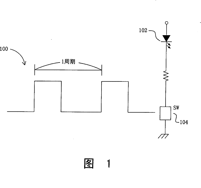
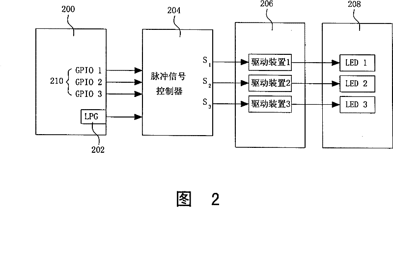
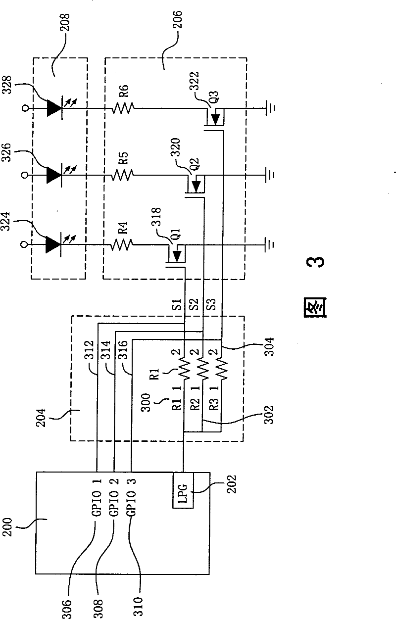
[0019] refer to figure 2 Shown is a block diagram of a control circuit according to a first embodiment of the present invention. In this embodiment, a central processing unit (Central Processing Unit) 200 with a built-in pulse signal generator (low pulse generator, LPG) 202 is used to control the flickering of the lights, wherein by controlling the general purpose of the central processing unit 200 The output / input state of the input / output pin (general purpose Input / Output, GPIO) 210 is used to select the lights to be flashed, and the pulse signal generated by the pulse signal generator 202 is used to trigger the selected lights. to flash. A pulse signal controller 204, according to the output / input status of the general-purpose input and output pin 210 of the central processing unit 200, triggers a specific driving device (driver) in the signal driver 206, and the signal received by the pulse signal controller 204 The pulse signal can control a specific light in the light...


PUM


Abstract

The invention relates to a light signal flash device and its operation method, comprising: a central processing unit with several general input / output pins while each one has itself resistance condition; a pulse signal generator connected to said central processing unit to generate a pulse signal; a pulse signal controller connected to the general input / output pins and the pulse signal generator;a drive circuit component with several drive circuits and connected to said pulse signal controller; and a light signal groups with several light sources which are connected to the drive circuit. Wherein, the pulse signal can trigger the drive circuit of said drive circuit component according to the resistance condition of general input / output pins to light the relative light source. Therefore, said invention can utilize the pulse signal generated by the pulse signal generator and the condition of general input / output pins to realize the purpose of flashing different light signals.

Description

technical field [0001] The present invention relates to a light signal control method and structure, in particular to a light signal flicker control method and its structure. Background technique [0002] In various electronic products, flashing lights are usually required to express various states. The method is to use such as figure 1 A low pulse signal 100 is shown to control a switch 104, and the light emitting diode 102 is periodically turned on to achieve the purpose of flickering. [0003] The traditional method of forming a pulse signal is generated by the program and the internal timer of the central processing unit, and the pulse signal is output through the general purpose input / output (General purpose Input / Output) pin of the central processing unit to control the switch, so as to control The lights flash. However, this method will keep the CPU in the operation mode all the time, which increases the power consumption of the electronic product, and needs to util...

Claims


Application Information

Patent Timeline
Patent Type & Authority Patents(China)
IPC IPC(8): H05B37/02
Inventor 蔡荣源陈国锋简崇安陈炜少
Owner HTC CORP
Why Eureka
Try Eureka