Engine transmission method for forklift

A technology of engines and forklifts, which is applied in the direction of machines/engines, transmissions, mechanical equipment, etc., and can solve problems such as complex structures, difficult spatial arrangements, and poor lubrication

Inactive Publication Date: 2006-03-01
浙江万丰车业有限公司
View PDF0 Cites 4 Cited by
  • Summary
  • Abstract
  • Description
  • Claims
  • Application Information

AI Technical Summary

Problems solved by technology

There is a hydraulic pump at the front end of the crankshaft of the existing engine, which adopts gear transmission, but the gear transmission has the disadvantages of complex structure, difficult space layout and poor lubrication due to the large number of gears.

Method used


Image

  • Engine transmission method for forklift
  • Engine transmission method for forklift
  • Engine transmission method for forklift

Examples


Embodiment Construction

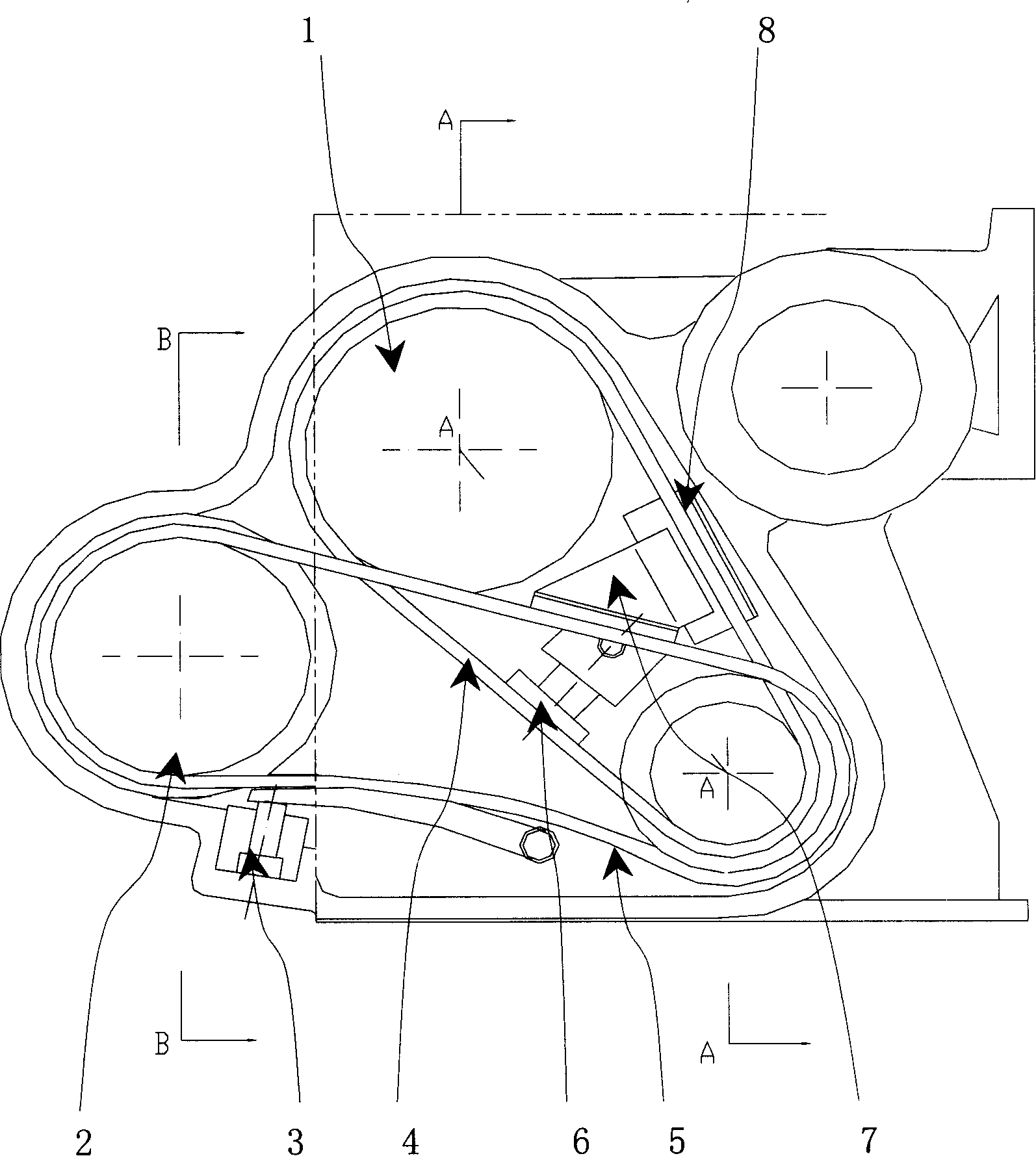
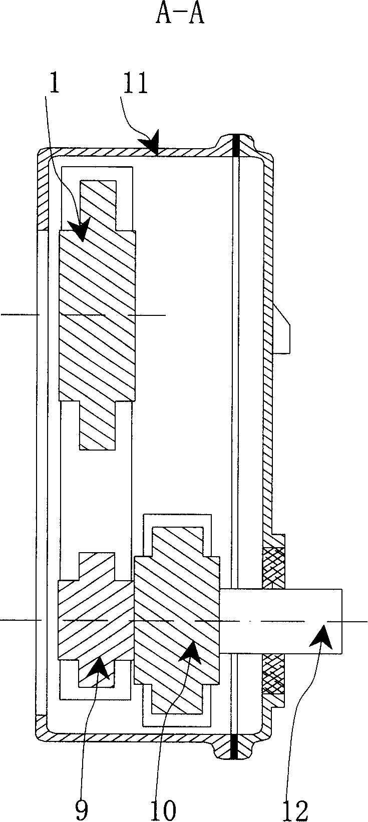
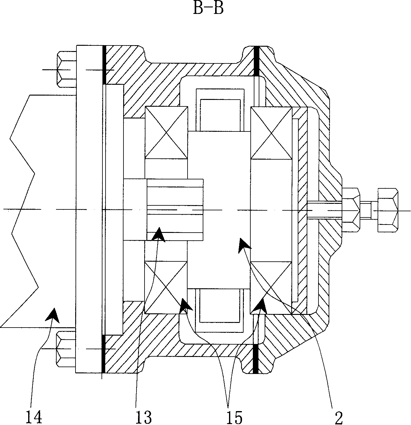
[0011] As shown in the figure, in the transmission method of an engine with a hydraulic pump for a forklift, in the sprocket chamber 11 of the engine with a hydraulic pump for a forklift, in order to keep the timing transmission ratio unchanged, the original timing roller chain 4 and the camshaft timing chain are used. Wheel 1, crankshaft timing sprocket 9, timing chain damper 8 and timing chain tensioner 6. The power transmission of the toothed chain is realized in this way: when the engine outputs power, the toothed power drive sprocket 10 installed on the crankshaft 12 is transmitted to the toothed power output sprocket 2 through the toothed chain 5, and the toothed power output The two ends of the sprocket are positioned with two bearings 15; because the spline shaft 13 of the hydraulic pump 14 has been inserted into the spline groove of the toothed power output sprocket, the hydraulic pump is driven when the toothed power output sprocket 2 rotates. 14 rotate synchronously...


PUM


Abstract

The engine transmission method for fork lift is one power transmission method with hydraulic pump, and realizes the power transmission by means of toothed chain transmission. One toothed chain transmission mechanism installed inside one chain wheel chamber has its driving force transmitted to the toothed output chain wheel via the toothed transmitting chain wheel installed on the crankshaft so as to drive the hydraulic pump. The present invention has great transmitted power to drive the hydraulic pump and unchanged timing function of the gasoline engine. The method has simple structure, smooth power transmission, lower noise, easy lubricating, high efficiency and other features.

Description

technical field [0001] The invention relates to a power transmission method of a forklift, in particular to a transmission method more suitable for an engine with a hydraulic pump used in a forklift. Background technique [0002] A forklift is a vehicle used for heavy lifting, which is different from a car in terms of function and working conditions. The speed of the forklift is limited, and the power is mainly used for lifting and unloading. The output power of the automobile engine is transmitted from the rear end of the crankshaft to the gearbox through the flywheel to drive the clutch to drive the front and rear axles; while 80% of the power of the forklift is to achieve the purpose of loading and unloading through the work of the oil cylinder. The front end realizes the power transmission output to drive the hydraulic pump to work. It is necessary to have multiple forms of power transmission output, which requires a transmission method that is more suitable for forkli...

Claims


Application Information

Patent Timeline
Patent Type & Authority Applications(China)
IPC IPC(8): F02B67/06F16H7/06F16H7/08
Inventor 汤治中刘勇潘清
Owner 浙江万丰车业有限公司
Why Eureka
Try Eureka