
Ejector capable of raising the cavitation performance of centrifugal pump

A technology for ejectors and centrifugal pumps, which is applied to components, pumps, and pump components of pumping devices for elastic fluids, and can solve problems such as complex structures, narrow working ranges, and ineffective cavitation performance

Inactive Publication Date: 2006-03-01
ZHEJIANG UNIV
View PDF0 Cites 19 Cited by
  • Summary
  • Abstract
  • Description
  • Claims
  • Application Information

AI Technical Summary

Problems solved by technology

Although the two-stage inducer achieves higher cavitation performance than the single-stage inducer, its working range is narrower than that of the single-stage inducer, and the axial length becomes longer and the structure is complicated.
At the same time, the parameters of some centrifugal pumps are not suitable for the structure of high-speed centrifugal pumps. For ordinary speed centrifugal pumps, the design of the inducer has almost no effect on improving the cavitation performance.

Method used


Image

  • Ejector capable of raising the cavitation performance of centrifugal pump
  • Ejector capable of raising the cavitation performance of centrifugal pump
  • Ejector capable of raising the cavitation performance of centrifugal pump

Examples


Embodiment Construction

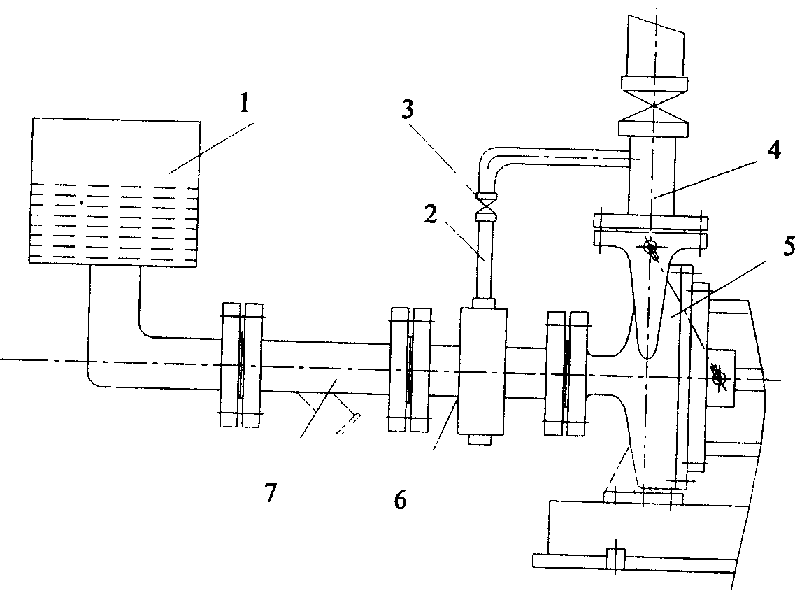
[0014] Such as figure 1 As shown, in the centrifugal pump of the present invention installed, the high-energy liquid at the outlet of the centrifugal pump 5 is led back to the ejector 6 before the pump inlet from the pump outlet discharge pipe 4 through the return pipeline 2 on the ejector circuit, and The front end of the injector 6 is connected to the water tank 1 through the inlet pipe 7, and the rear end is connected to the inlet of the pump. The size of the return flow is adjusted by valve 3. The ejector and the pump body of the centrifugal pump are connected by bolts.

[0015] The present invention is installed before the inlet of the centrifugal pump 5, and part of the high-energy liquid at the outlet of the centrifugal pump is led back to the ejector 6 through the ejector circuit between the outlet discharge pipe 4 of the centrifugal pump 5 and the ejector interface 9 of the ejector 6. The injection interface 9, the fluid introduced back from the injection interface ...


PUM


Abstract

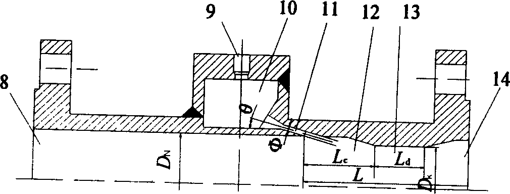
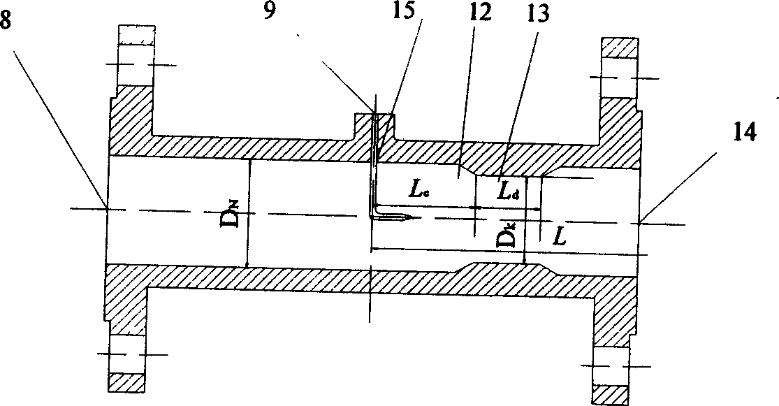
The ejector capable of raising the cavitation performance of centrifugal pump includes successively ejecting inlet, mixing section, diffusion section and ejecting outlet. There are annular cavity around the ejecting inlet, ejecting interface on the annular cavity, several axial inclined ejecting nozzles in axial angle of 10-45 deg distributed homogeneously on the side wall of the annular cavity. Or, the ejecting interface has axial straight ejecting nozzle connected with the ejecting direction coincided with the central axis of the ejector. For high speed centrifugal pump, combined structure of inducing wheel and ejector is adopted, and for common centrifugal pump, ejector is adopted directly in obtaining optimal cavitation performance. The centrifugal pump with ejector may be used in conveying acids, alkalis, salts, alcohols, medicine solution and other liquid medium containing solid particle in the temperature of ¿C200 to +400 deg.c, especially those with strict cavitation performance requirement.

Description

technical field [0001] The invention relates to a fluid conveying machine, in particular to an ejector capable of improving the cavitation performance of a centrifugal pump. It uses injection technology to improve the cavitation performance of centrifugal pumps, and is an organic combination of jet pumps and centrifugal pumps. Background technique [0002] Cavitation damage is an important cause of centrifugal pump failure. Once the cavitation damage occurs in the centrifugal pump, not only the performance of the pump cannot meet the requirements, but also the pumping and vibration damage will occur, so that the pump cannot work normally. With the development of high-speed centrifugal pumps and the variety of easily vaporized media to be transported, higher and higher requirements are put forward for the cavitation performance of pumps. [0003] There are two ways to improve the cavitation performance of the centrifugal pump. One is to increase the NPSH of the device. a ,...

Claims


Application Information

Patent Timeline
IPC IPC(8): F04F5/10F04D29/66
Inventor 朱祖超崔宝玲
Owner ZHEJIANG UNIV
Learn More