
Method for using chaos frequency-modulated signal as pulse compression Radar signal source

A technology of pulse compression radar and frequency modulation signal, which is applied in the direction of utilizing re-radiation, radio wave reflection/re-radiation, measuring devices, etc. It can solve the problems of difficult processing, single linear frequency modulation signal waveform, and limited anti-interference performance, and achieve high Effect of anti-interference performance

Active Publication Date: 2006-03-01
INST OF ELECTRONICS CHINESE ACAD OF SCI
View PDF0 Cites 21 Cited by
  • Summary
  • Abstract
  • Description
  • Claims
  • Application Information

AI Technical Summary

Problems solved by technology

The chirp signal has a single waveform and cannot perform waveform agility. The anti-interference performance is limited: binary pseudo-random sequences include m-sequences, Bark sequences, etc., and the aperiodic autocorrelation characteristics of m-sequences are not good, and the length and number of Bark sequences are limited. Limits the detection distance and speed resolution of radar: Although the noise signal has an infinite length in theory, it can make up for the defect of the pseudo-random binary sequence, but it is difficult to process

Method used


Image

  • Method for using chaos frequency-modulated signal as pulse compression Radar signal source
  • Method for using chaos frequency-modulated signal as pulse compression Radar signal source
  • Method for using chaos frequency-modulated signal as pulse compression Radar signal source

Examples


Embodiment Construction

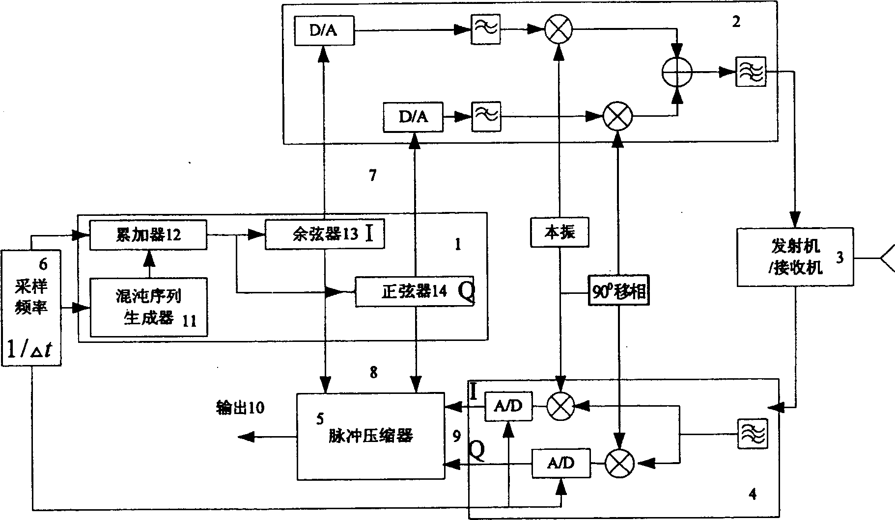
[0026] figure 1 It is a system block diagram of the present invention. It can be seen from the figure that the system is divided into signal generation unit 1, modulation unit 2, transmitting / receiving unit 3, demodulation unit 4 and pulse compression unit 5. Among them, signal generation unit 1 includes chaotic sequence generator 11, accumulator 12. A sine 14 and a cosine 13. The output terminal of the chaotic sequence generator 11 is electrically connected to the accumulator 12, and the output terminals of the accumulator 12 are electrically connected to the sine generator 14 and the cosine generator 13 respectively. One output of the sine 14 and cosine 13 is electrically connected to the modulation unit 2 via the line 7 , and the other output is electrically connected to the pulse compression unit 5 via the line 8 . The modulation unit 2, the transmitting / receiving unit 3, the demodulation unit 4 and the pulse compression unit 5 are electrically connected in sequence. A ...


PUM


Abstract

The invented method includes the following steps: 1). Inputting the selected parameter into high-speed DSP to produce chaos series; 2). Using chaos series to make frequency modulation to obtain chaos radar signal; 3). Dividing chaos radar signal into two lines, one line is passed through modulation unit and transferred to transmitter and transmitted, another line is transferred to pulse compression unit and can be used as reference signal; and 4). Transferring base band signal after the received return signal is down converted to the pulse compression unit to make pulse compression, then outputting said signal for making analysis.

Description

technical field [0001] The invention belongs to the technical field of pulse compression radar systems, in particular to pulse compression radar systems using noise, pseudo-random sequences and chaotic sequences as modulation signals. Background technique [0002] The modulation signals used in traditional pulse compression radar include linear frequency modulation signal, nonlinear frequency modulation signal, pseudo-random binary sequence and noise signal. The chirp signal has a single waveform and cannot perform waveform agility. The anti-interference performance is limited: binary pseudo-random sequences include m-sequences, Bark sequences, etc., and the aperiodic autocorrelation characteristics of m-sequences are not good, and the length and number of Bark sequences are limited. Limiting the detection distance and speed resolution of radar: Although the noise signal has an infinite length in theory, it can make up for the defect of the pseudo-random binary sequence, but...

Claims


Application Information

Patent Timeline
IPC IPC(8): G01S7/28G01S13/00
Inventor 丁凯杨汝良
Owner INST OF ELECTRONICS CHINESE ACAD OF SCI
Learn More