Non-blending spinal side bending corrector

A scoliosis, non-fusion technology, applied in the direction of internal bone synthesis, internal fixator, fixator, etc., can solve problems such as large span, prolapse of nails, and few fixation points, so as to reduce operation time, avoid stress concentration, avoid Effects of Spinal Injury

Inactive Publication Date: 2006-03-15
王岩 +2
View PDF0 Cites 11 Cited by
  • Summary
  • Abstract
  • Description
  • Claims
  • Application Information

AI Technical Summary

Problems solved by technology

In addition, due to the small number of fixed points and the large span, it is necessary to wear a brace fo

Method used


Image

  • Non-blending spinal side bending corrector
  • Non-blending spinal side bending corrector
  • Non-blending spinal side bending corrector

Examples


Embodiment Construction

[0029] The technical scheme of the present invention will be described in detail below in conjunction with the accompanying drawings.

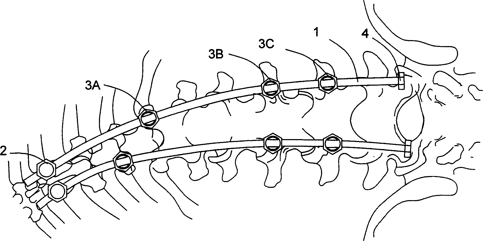
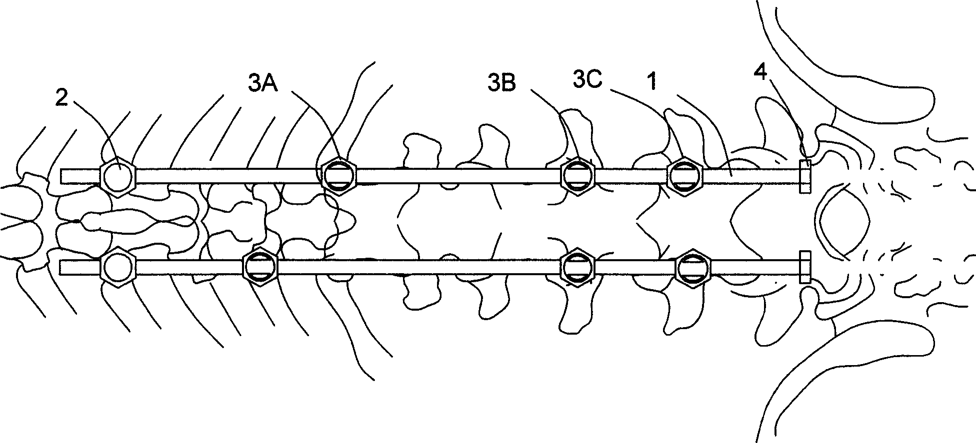
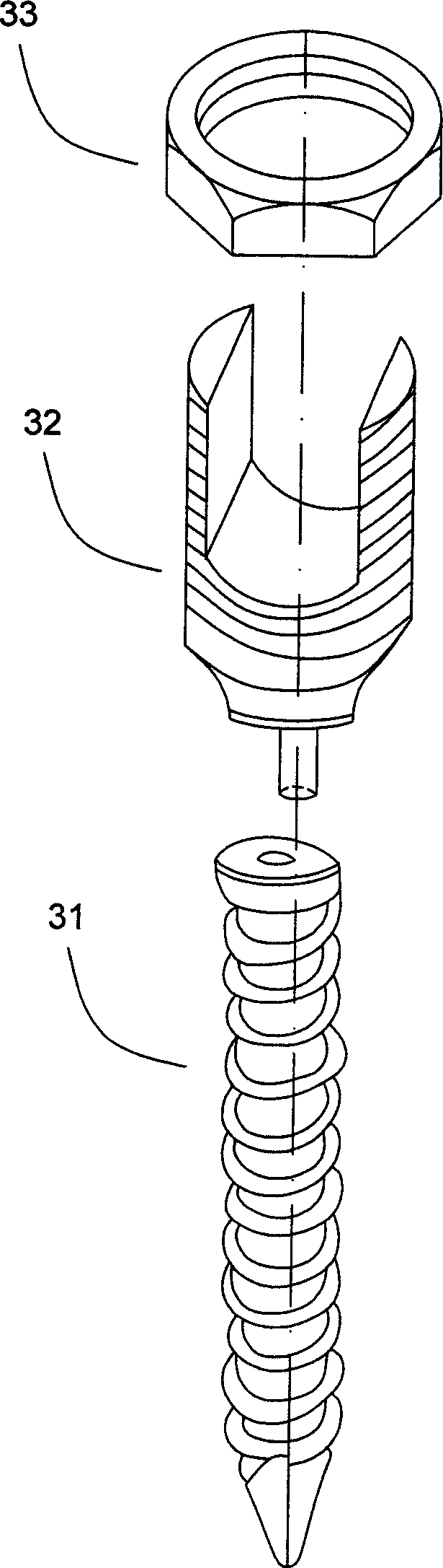
[0030] Figure 1~3 It is a schematic diagram of the structure of the present invention. Such as figure 1 As shown, the non-fusion scoliosis correction device of the present invention includes a fixation screw 2 , a pedicle screw 3 and a correction rod 1 . The fixation nail 2 is fixed on the fixed vertebra of the lower spine, usually the fixation nail is fixed between the thoracic segment and the lumbar segment, and is fixedly connected with the lower end of the correction rod 1 to form a screw rod lock with a stable structure, which can control the direction and rotation of the correction rod 1 Tight connection structure. The pedicle screws 3 are sequentially fixed on the vertebral bodies in the range of scoliosis, and are sequentially slidably connected with the correction rod 1 to form a screw-rod sliding connection structure that realize...


PUM


Abstract

A device for correcting the non-fusion scoliosis is composed of a correcting rod, the fixing nail fixed to the curved spine and locked to the said correcting rod, and multiple nails for pediculus arcus vertebrae, which are linked with said correcting rod in slide mode. Its advantage is 3D correcting effect.

Description

technical field [0001] The invention relates to an internal fixation device for treating scoliosis, in particular to an internal fixation device for treating scoliosis patients with growth potential. Background technique [0002] Scoliotic deformity seriously affects the patient's appearance, organ function, social adaptability, and even life expectancy. Therefore, surgical correction is required if brace treatment is ineffective. At present, the main surgical method is fusion and fixation, but for scoliosis patients with growth potential, if the spinal instrument fixation plus spinal fusion is performed too early, it will seriously affect the normal development and growth of the children. The current method is the adjustable spinal growth valve technology, and the postponement of spinal fusion. However, the fixation device needs to be stretched and extended regularly to continuously adapt to the growth of the child's spine and achieve continuous correction. [0003] The c...

Claims


Application Information

Patent Timeline
IPC IPC(8): A61B17/58A61B17/70
Inventor 王岩张雪松王征
Owner 王岩
Why Eureka
Try Eureka