
Pipe connecting structure

A technology for connecting structures and pipelines, applied in the direction of pipeline layout, etc., can solve the problems of poor connection, damaged sealing ring, unreliable construction of missed inspection, etc., and achieve the effect of good workability

Inactive Publication Date: 2006-03-15
KYORITSU EATETABUKU
View PDF1 Cites 0 Cited by
  • Summary
  • Abstract
  • Description
  • Claims
  • Application Information

AI Technical Summary

Problems solved by technology

Therefore, after construction, it is difficult to visually confirm whether the pipe connection port 94 of the chamber 96 and the opening of the pipe 97 are misaligned with each other, and unreliable construction may be missed.
[0007] In addition, during the connection work of the pipes, the flange 97a of the pipe 97 slides in a state of surface contact with the U-shaped groove fixing plate 98, so the frictional resistance may become large.
In addition, during the connection work, the sealing ring (not shown) provided around the pipe connection port 94 of the chamber 96 and the flange 97a of the pipe 97 are in sliding contact with each other, so the sealing ring may be damaged, resulting in poor connection.

Method used


Image

  • Pipe connecting structure
  • Pipe connecting structure
  • Pipe connecting structure

Examples


Embodiment Construction

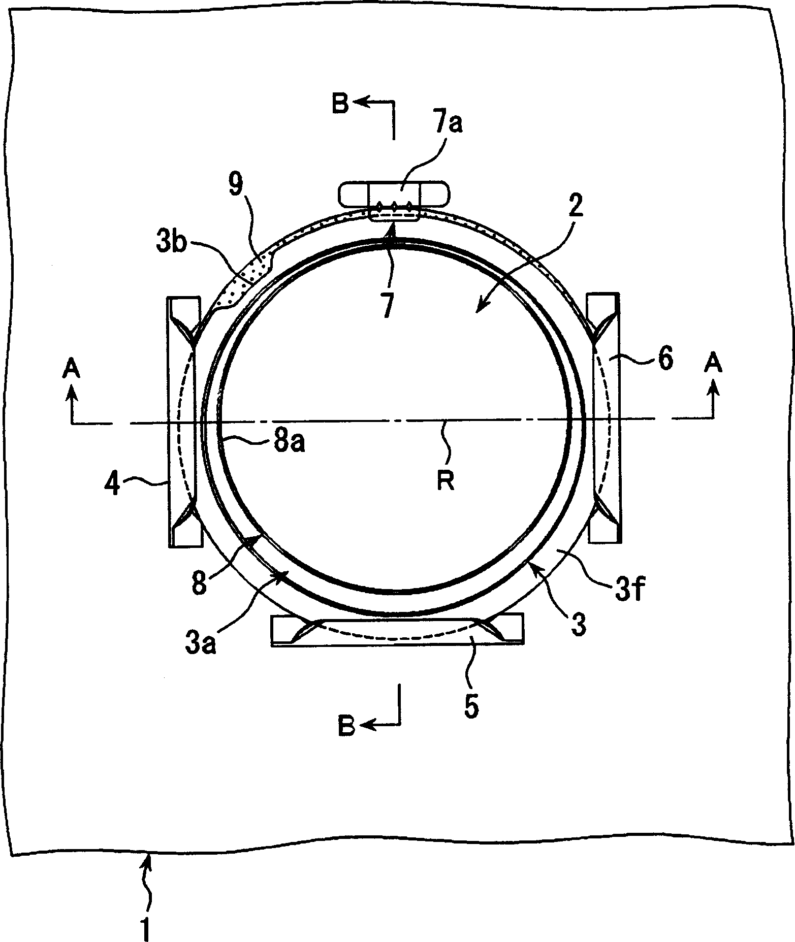
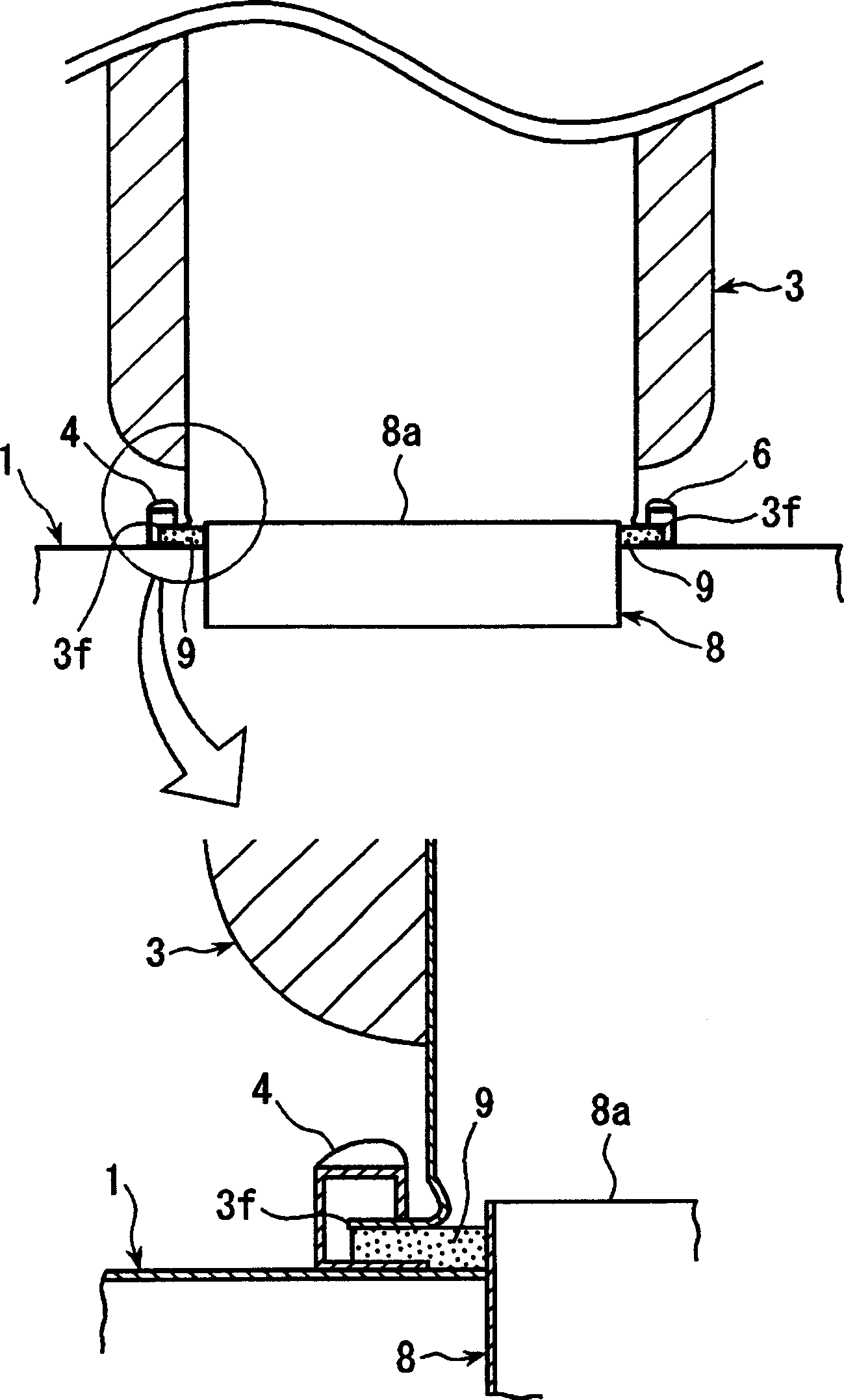
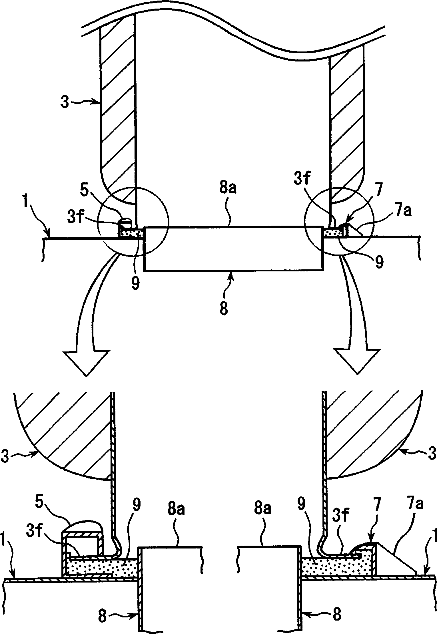
[0047] figure 1 It is a partially omitted front view showing a pipe connection structure according to an embodiment of the present invention; figure 2 yes figure 1 A sectional view along line A-A of ; image 3 yes figure 1 The sectional view along the B-B line; Figure 4 is the composition figure 1 Partial cut-away side view of the pipe of the shown pipe connection structure; Figure 5 yes means Figure 4 a drawing of the opening of the duct shown; Figure 6 is the composition figure 1 The front view near the pipe connection port of the shown pipe connection structure; Figure 7 is along Figure 6 Sectional view of line C-C; Figure 8 is along Figure 6 Sectional view of line D-D.

[0048] Such as Figure 1 ~ Figure 3 As shown, the duct connection structure of this embodiment is a connection structure provided at the duct connection port 2 of the hollow box-shaped air conditioner 1 and the opening 3a of the cylindrical duct 3 . In this duct connection struc...


PUM


Abstract

In the invention, the opening part of the barrel duct is disposed in relative position to the duct-connecting port of the air-conditioning machine in the part of connecting the duct-connecting port in the air-conditioning machine and the opening part of the barrel duct. A peripheral flange of the opening part in the barrel duct is pressed in the direction of pressing the air-conditioning machine and held using three pressing members and a fixing member. The three pressing members are disposed at a 90deg. space in the lower semi-cycle area including the duct-connecting port and the fixing member is disposed in the upper semi-cycle area.

Description

technical field [0001] The present invention relates to a connection structure between various air-conditioning equipment and ducts constituting chambers, fan coil units, air outlets, etc. of air-conditioning equipment installed in office buildings, large stores, and the like. Background technique [0002] Air-conditioning equipment installed in buildings such as office buildings and large stores consists of various air-conditioning devices for supplying, distributing, or blowing conditioned air to each room. When carrying out the installation and construction of these air-conditioning equipment, such as Figure 13 As shown, the lower end portion of a suspension bolt 91 suspended from the ceiling is passed through a suspension member 92 provided in a chamber 90 and the like, and a nut 93 is screwed into the suspension bolt 91 to fix the chamber 90 and the like. Then, the opening 95a of the pipe 95 is made to face the pipe connection port 94 of the chamber 90, and the pipe co...

Claims


Application Information

Patent Timeline
Patent Type & Authority Applications(China)
IPC IPC(8): F24F13/02
Inventor 久野幸男上野武司近藤圭一龙头健
Owner KYORITSU EATETABUKU
Learn More