Oriented coupler of coupler wire and production thereof
A technology of directional coupler and coupled line, which is applied in the field of communication, can solve problems such as failure to meet conventional requirements, and achieve the effects of enhancing directivity, increasing power capacity, and shortening length
- Summary
- Abstract
- Description
- Claims
- Application Information
AI Technical Summary
Problems solved by technology
Method used
Image

Examples
no. 1 example
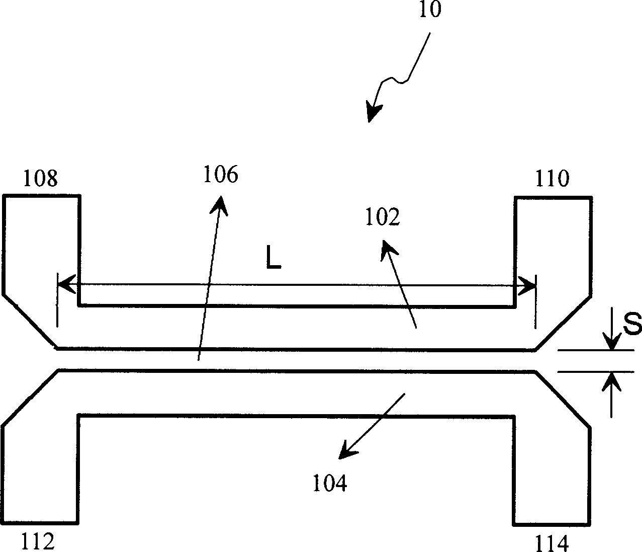
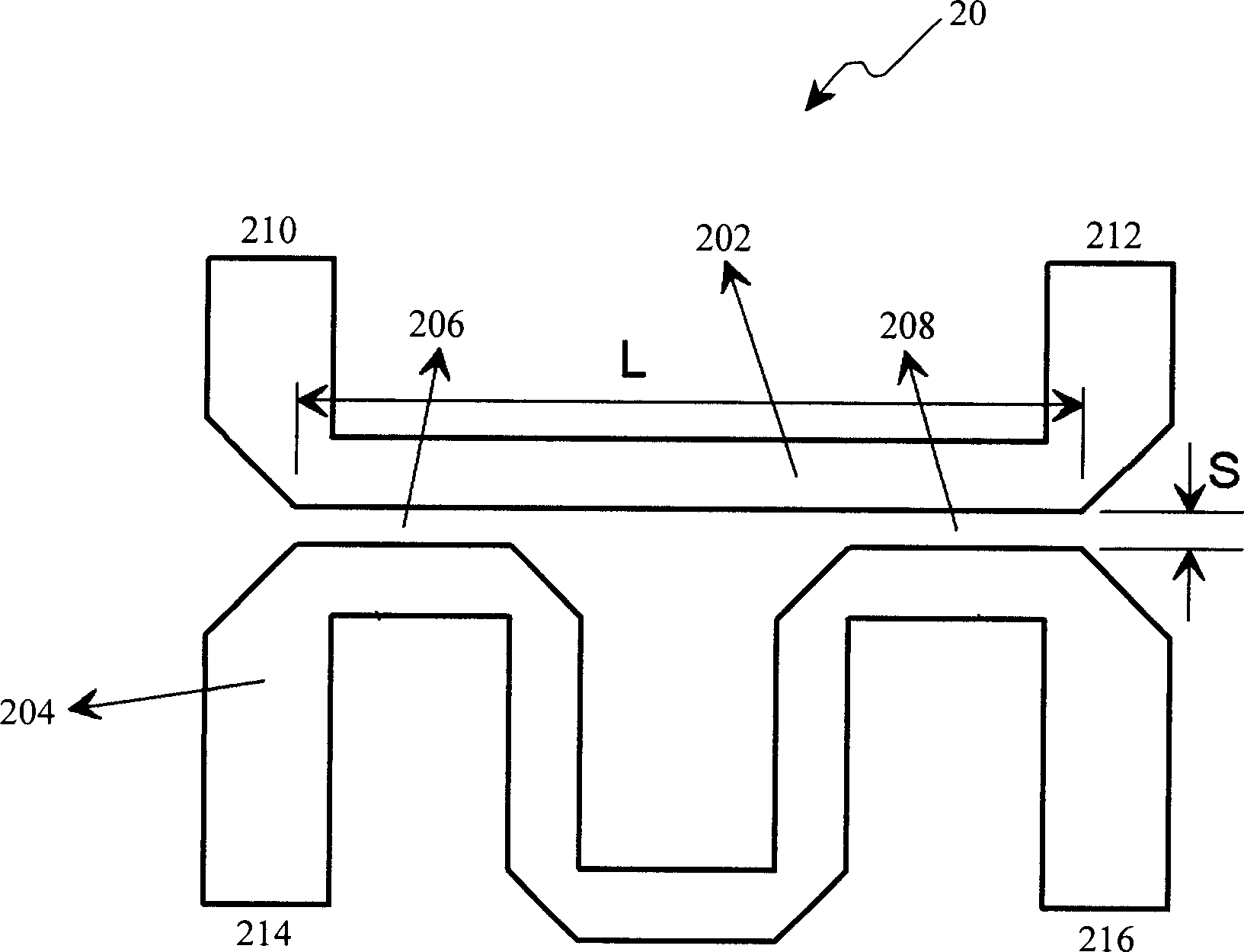
[0044] figure 2 A schematic diagram of a coupled line directional coupler 20 according to a first embodiment of the present invention is shown.
[0045] The coupled line directional coupler 20 according to the first embodiment of the present invention includes a main signal line 202 and a coupled signal line 204 coupled to each other. The main signal line 202 has a first port 210 for receiving the main signal and a first port 210 for outputting the main signal. The third port 212 of the coupled signal line has a second port 214 for outputting the first coupled signal and a fourth port 216 for outputting the second coupled signal. Two main signal lines 202 and the coupled signal line 204 are formed. Two coupling regions: a first coupling region 206 and a second coupling region 208 . The length L of the main signal line 202 is far less than 25% of the guide wavelength, thus greatly reducing the transmission loss of the main signal line. Since the main signal line transmits a h...
no. 2 example
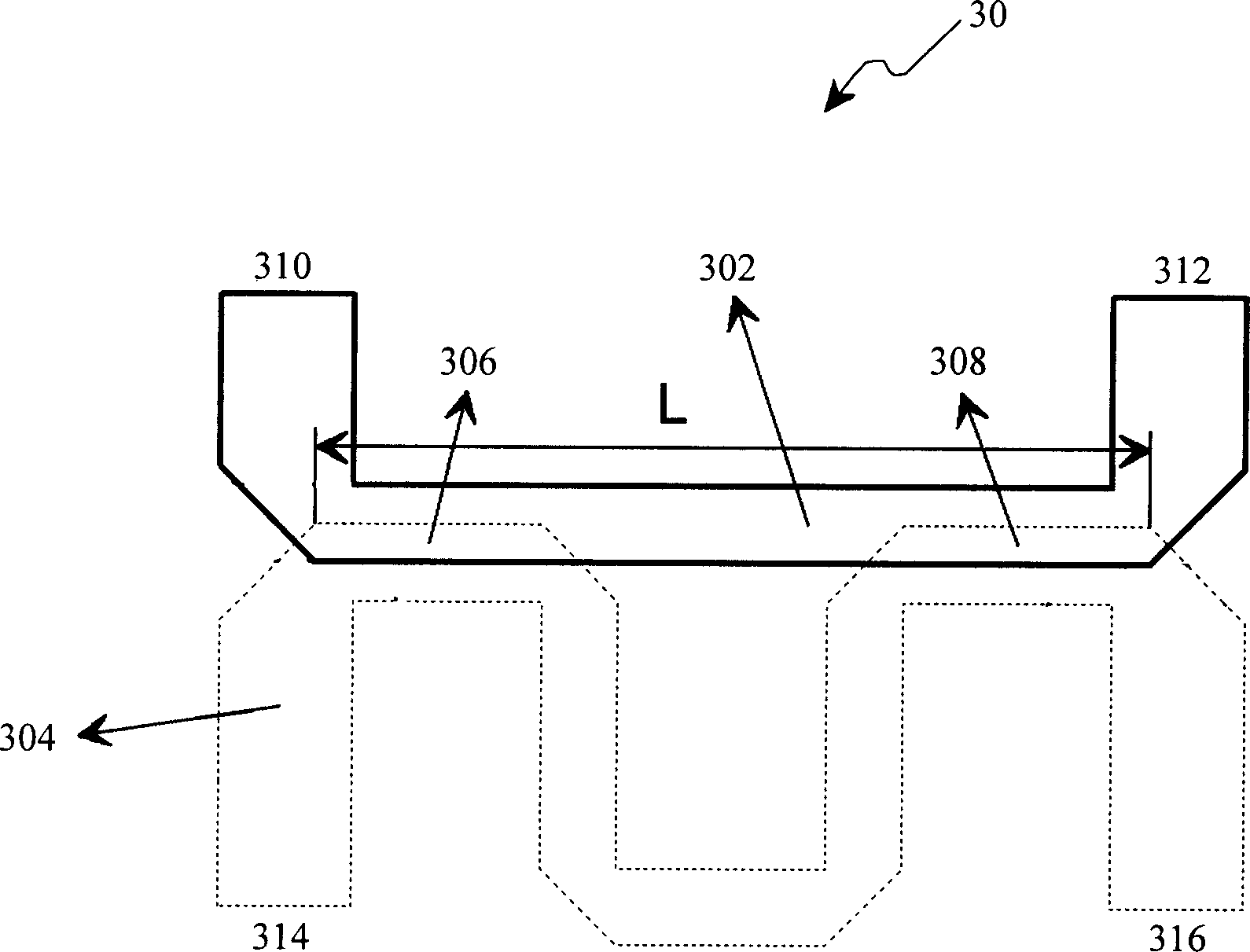
[0048] image 3 A schematic diagram of a coupler 30 according to a second embodiment of the invention is shown. According to the coupler 30 of the second embodiment of the present invention and figure 2 The difference of the illustrated coupler 20 according to the first embodiment of the present invention is that the main signal line 302 and the coupled line 304 are not on the same plane. like image 3 As shown, the coupled signal line 304 is drawn with a dashed line, indicating that the coupled signal line 304 is not coplanar with the main signal line 302 . The projection areas of the two are partially overlapped, and of course may not overlap. The main signal line 302 and the coupling signal line 304 are coupled together, and two coupling regions are formed between them: a first coupling region 306 and a second coupling region 308 . The length L of the main signal line 302 is far less than 25% of the guide wavelength, thus greatly reducing the transmission loss of the m...
no. 3 example
[0050] Figure 4 A schematic diagram of a coupler 40 according to a third embodiment of the invention is shown. The coupler 40 also includes a main signal line 402 and a coupled signal line 404 coupled to each other, and figure 2 The difference of the shown coupler according to the first embodiment of the present invention is that the first coupling region 406 and the second coupling region 408 are connected by several elements or groups of elements 410, for example, resistors may be used to connect these The two coupling regions can also be directly connected by a transmission line, and those skilled in the art should understand that other connection elements can also be used. Other aspects of the coupler according to the third embodiment of the present invention are the same as those according to the first embodiment of the present invention.
PUM
 Abstract
Description
Claims
Application Information
 - Generate Ideas
- Intellectual Property
- Life Sciences
- Materials
- Tech Scout
- Unparalleled Data Quality
- Higher Quality Content
- 60% Fewer Hallucinations
Browse by: Latest US Patents, China's latest patents, Technical Efficacy Thesaurus, Application Domain, Technology Topic, Popular Technical Reports.
© 2025 PatSnap. All rights reserved.Legal|Privacy policy|Modern Slavery Act Transparency Statement|Sitemap|About US| Contact US: help@patsnap.com