Material feeding pushing aid device for tube bending machine

A tube bending machine and boosting technology, which is applied to the feeding device, positioning device, storage device, etc., can solve the problems of low precision, bulging, and pipe slippage, and achieve high quality, high transmission precision, and simple mechanical structure. Effect

Inactive Publication Date: 2006-03-22
JIANGSU HEFENG MECHANICAL MAKING
View PDF0 Cites 22 Cited by
  • Summary
  • Abstract
  • Description
  • Claims
  • Application Information

AI Technical Summary

Problems solved by technology

The above-mentioned feeding device drives the pipe to move forward synchronously with the bend. Its main function is to prevent the pipe from wrinkling and bending due to the large friction between the pipe, the mold and the mandrel when the pipe is bent and deformed. Defects such as uneven deformation, but because most of the traditional feeding transmission me

Method used


Image

  • Material feeding pushing aid device for tube bending machine
  • Material feeding pushing aid device for tube bending machine

Examples


Embodiment Construction

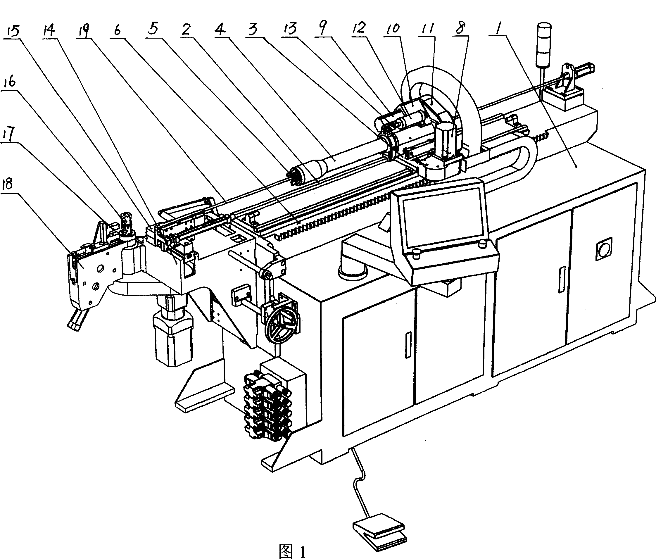
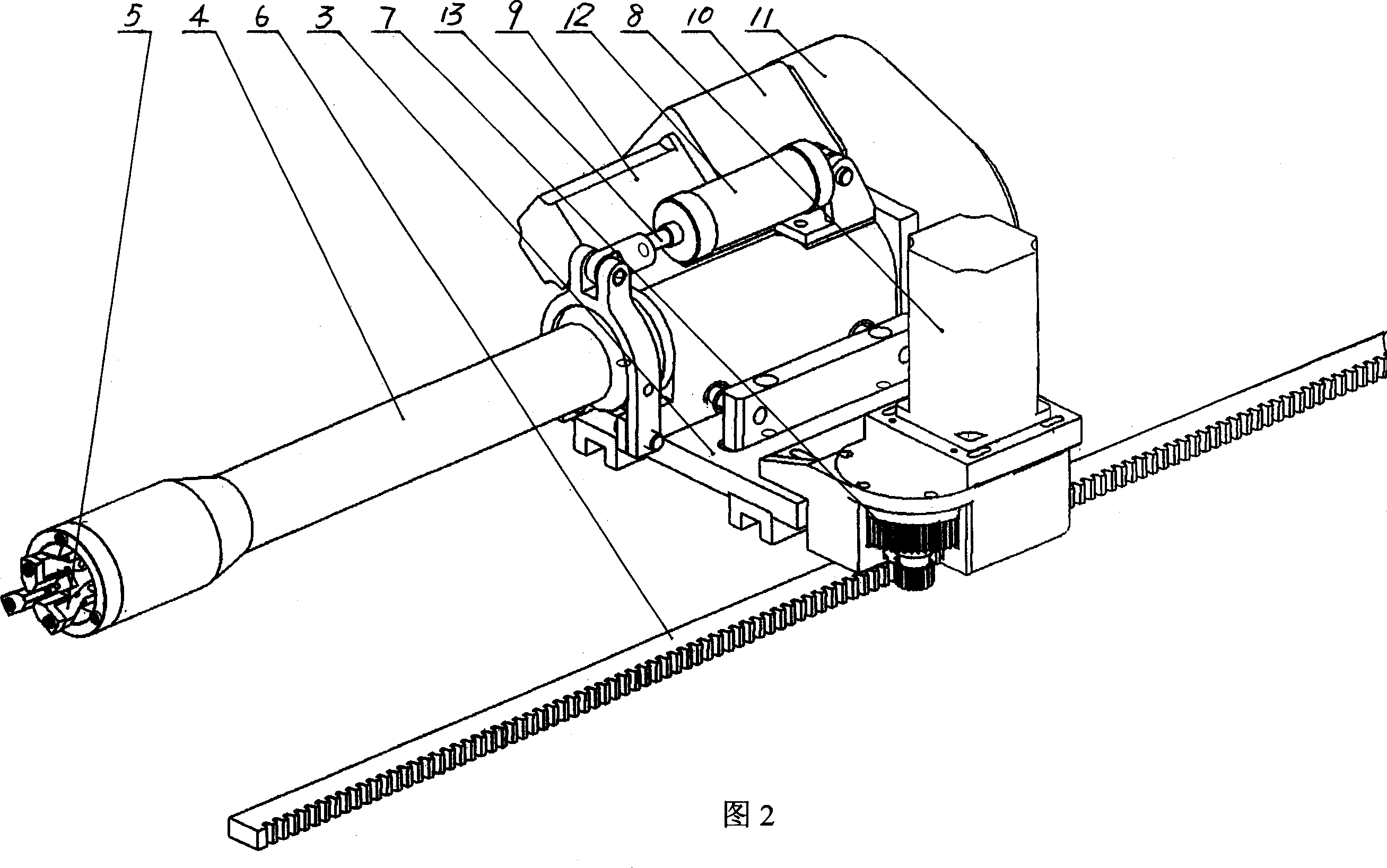
[0010] As shown in Figures 1 and 2, a feeding booster device for a pipe bender includes a feeding trolley 3 arranged on the guide rail 2 of the fuselage 1, a push-tight sleeve 4 and its transmission device arranged on the feeding trolley 3, and are arranged on the Push the clamp 5 at the end of the sleeve 4 and its driving device, a rack 6 is arranged on one side of the guide rail 2, and a gear 7 meshing with the rack 6 is arranged on the bottom side of the corresponding feeding trolley 3, and the gear 7 is driven by The device is connected with the servo motor 8, the servo motor 8 is connected with the computer automatic control device, and the computer automatic control device is not drawn in the figure; The rotary tube motor 9, the reduction gear 10 and the rotary tube gearbox 11 on the trolley 3 are composed, and the push-tight sleeve 4 is connected with the rotary tube gearbox 11; the driving device of the clamp 5 is also the prior art, which is usually a The clamping cyl...


PUM


Abstract

The material feeding push assister for tube bending machine includes feeding bogie on the tracks, pushing sleeve on the bogie and its driver, clamp in the end of the pushing sleeve and its driver, rack on one side of the tracks to mesh with the gear in the feeding bogie, servo motor connected to the gear via transmission unit, and automatic computerized controller connected with the servo motor. The present invention has simple structure, high transmission precision, constant force pushing of the fed material and high tube bending quality.

Description

technical field [0001] The invention relates to a feeding device of a pipe bender, in particular to a feeding constant force booster of a pipe bender. Background technique [0002] The structure of the existing pipe bending machine generally includes the body of the pipe bending machine, the feeding device arranged on the guide rail of the body, the head set at the end of the body, and the top clamping mechanism and the wheel die set on the head. The feeding device includes a feeding trolley slidingly arranged on the guide rail of the fuselage, a feeding transmission mechanism set on the feeding trolley, a push-tight sleeve, and a transmission that drives the push-tight sleeve to rotate. The device and the clamp arranged at the end of the push sleeve, the clamp is driven by a clamping cylinder arranged at the rear of the push sleeve, the above-mentioned feeding transmission mechanism uses a motor to drive the belt transmission device, and then drives the feeding trolley on t...

Claims


Application Information

Patent Timeline
IPC IPC(8): B21D43/02B21D9/16
Inventor 林洪才林永才赵叶静陈如洋马向阳
Owner JIANGSU HEFENG MECHANICAL MAKING
Why Eureka
Try Eureka