
Roll-up heating for a floor, or wall

A heating device and floor technology, which is applied to household heating, electric heating devices, applications, etc., can solve problems such as being unsuitable for direct use and damaging heating elements.

Active Publication Date: 2006-03-22
DANFOSS AS
View PDF1 Cites 11 Cited by
  • Summary
  • Abstract
  • Description
  • Claims
  • Application Information

AI Technical Summary

Problems solved by technology

[0003] The known roll-up floor heating has the disadvantage that it is not suitable for direct use under all kinds of floor coverings, since the forces acting on the floor covering are transmitted via the floor covering to the floor heating , may damage the heating element

Method used


Image

  • Roll-up heating for a floor, or wall
  • Roll-up heating for a floor, or wall
  • Roll-up heating for a floor, or wall

Examples


Embodiment Construction

[0009] The preferred embodiments of the present invention are described in detail in the appended claims.

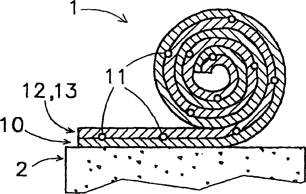
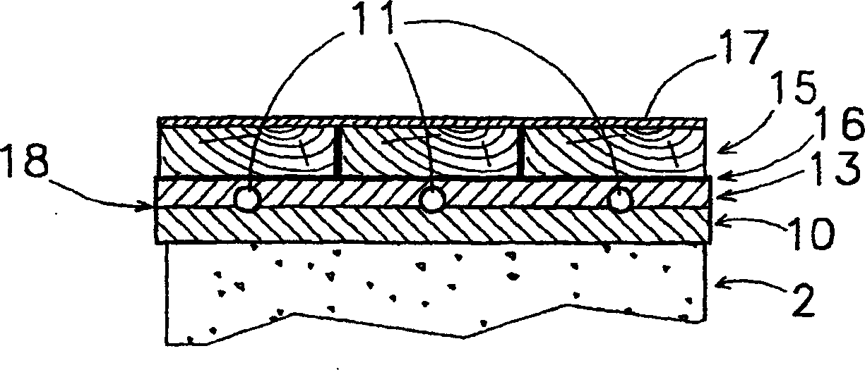
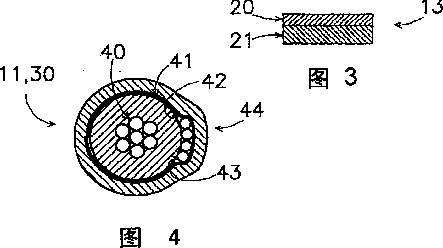
[0010] In one embodiment, the elastic modulus of the side of the force distribution layer facing the heat insulating layer is smaller than the other side thereof, specifically, the elastic modulus is at most 67% of the other side. Specifically, the force distribution layer includes a first layer and a second layer. The second layer faces the heat insulating layer. The elastic modulus of the first secondary layer is greater than that of the second elastic secondary layer. Due to the difference in elastic modulus, when a force is applied to a point on the force distribution layer, a higher pressure will be generated on the side farther from the heat insulating layer (specifically, on the first layer). The pressure is substantially in the plane of the force distribution layer, so that the top surface of the force distribution layer sags over a larger surface area. In this way, ...


PUM


Abstract

The roll-up heating (1) for a floor, or wall, comprises an insulating layer (10), a heating element (11) and a cladding (12). The insulating layer (10) is intended for laying on a floor (2) and the heating element (11) extends between the cladding (12) and the insulating layer (10). The cladding (12) is intended to support a floor covering (15) and comprises a force distribution layer (13) for transmitting a force which is exerted on the cladding (12) in a distributed manner to the insulating layer (10). In as far as (a part of) the heating element (11) is at the location or in the vicinity of the exerted force, the load which will be exerted on it will be lower than the original load, due to the force being transmitted in a distributed manner. This lowers the risk of the heating element (11) being damaged.

Description

Technical field [0001] The invention relates to a roll-up heating device for floors or walls. Background technique [0002] U.S. Patent No. 3,539,767 discloses in Fig. 11 a rollable floor heating device composed of several layers. Among them, conductive metal flakes are used as heating elements. Use polyvinyl chloride glue to glue this metal foil between the liner and the thin paper cover. During and after the manufacturing process, this floor heating device can be rolled up and transported to a room where it can be used as a floor heating device once it is unfolded in the room. [0003] The disadvantage of the known roll-up floor heating device is that it is not suitable for direct use under all kinds of floor coverings. This is because the force applied to the floor covering will be transmitted to the floor heating device through the floor covering. , May damage the heating element. [0004] The purpose of the present invention is to at least partially eliminate the above-menti...

Claims


Application Information

Patent Timeline
Patent Type & Authority Applications(China)
IPC IPC(8): F24D13/02H05B3/06H05B3/56H05B3/36
CPCH05B2203/016H05B2203/003H05B2203/026F24D13/022H05B3/36Y02B30/26Y02B30/00F24D13/02F24D13/00
Inventor 罗伯特·奥斯特林
Owner DANFOSS AS
Learn More