
Coin counter

A coin machine and coin technology, which is applied in the direction of handling coins or valuable banknotes, instruments, etc., can solve the problems of time-consuming and labor-intensive coins

Inactive Publication Date: 2006-03-22
王新东
View PDF0 Cites 3 Cited by
  • Summary
  • Abstract
  • Description
  • Claims
  • Application Information

AI Technical Summary

Problems solved by technology

[0003] In order to overcome the time-consuming and labor-intensive shortcomings of manually counting coins, I invented a time-saving and accurate coin counting machine

Method used


Image

  • Coin counter
  • Coin counter
  • Coin counter

Examples


Embodiment Construction

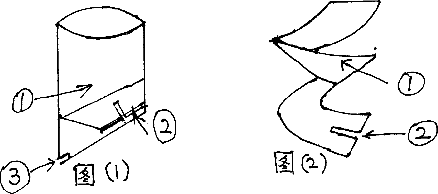
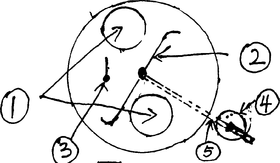
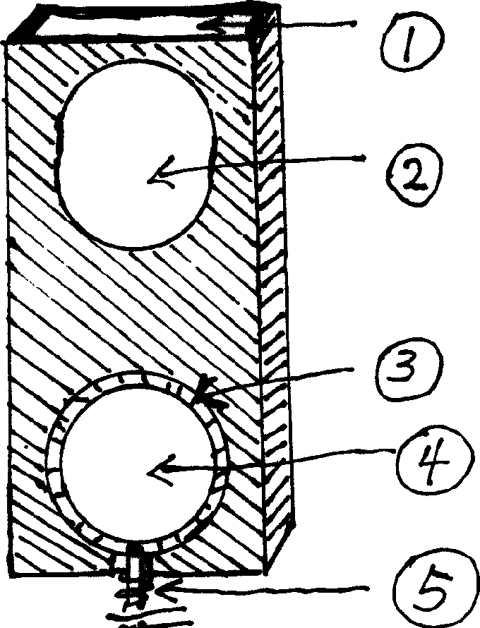
[0018] Pour the coin into 1 in Figure 1, the coin passes through the chute from the spiral blade in Figure 2 to the inclined rotating disk, insert Figure 8 AC voltage of 220V, via B 1 Step down, rectify and filter, get 12V DC power supply (12V battery can also be used), connect K 1 Power on, display on, trigger K 3 , capacitance C 2 charging, through resistor R 6 charging, BG 3 cut-off, transistor BG 1 Conduction, the meter J starts to pull in, the working indicator light is on, the motor drives the tilting disc to rotate, and the coins that are freely placed on the rotating disc can pass under the coin baffle (because the parallel distance between the coin baffle and the rotating disc is only less than the coin Slightly larger), flat coins slide into the bottom of the barrel from the swash plate, and come out from 3 in Figure 1, and enter the counterfeit coin detector (remove the counterfeit coin), and the real coin can enter Figure 4 entry 1, image 3 The elastic bar...


PUM


Abstract

The coin counter capable of screening and counting coins has one barrel with spiral blades and rotatable inclined holed circular disc in the bottom to screen out coins with size smaller; false coin recognizer; coil arranging flat tube to arrange coins in the bottom and with hitting hammer to turn on the switch until the coin is set inside the coin tube with card; notched wheel to obtain the switching signal and display. The present invention can count coins accurately.

Description

Technical field: [0001] The present invention is a kind of machine that accurately counts out the quantity of various coins in the world. Background technique: [0002] At present, the various coins circulating in the market are large in quantity and small in face value, so manual counting is very troublesome and inaccurate. Invention content: [0003] In order to overcome the time-consuming and labor-intensive shortcoming of manually counting coins, I invented a time-saving and accurate coin counting machine. It also keeps coins aligned (for easy bundling) and distinguishes between different coins and counterfeit money. It can automatically stop after counting coins, and it can be used for both direct and direct use. [0004] The technical scheme adopted in the present invention is: a helical blade is installed in a cylindrical barrel, the bottom is a rotatable inclined disc, and a movable elastic strip smaller than the diameter and parallel to the disc is installed at ...

Claims


Application Information

Patent Timeline
IPC IPC(8): G07D13/00
Inventor 王新东
Owner 王新东
Learn More