Batch production device, batch, and press form mounting method in batch production device

A technology of manufacturing device and extrusion die, applied in the field of badge manufacturing device, can solve the problems of moving drawing paper, unable to bend the surface plate, unable to manufacture uniformly, etc.

Active Publication Date: 2006-03-22
BANDAI CO LTD +1
View PDF1 Cites 11 Cited by
  • Summary
  • Abstract
  • Description
  • Claims
  • Application Information

AI Technical Summary

Problems solved by technology

When the periphery of the surface plate is bent by the straight inclined side, the surface plate cannot be bent into a dome because the periphery of the surface plate is bent approximately at right angles to the bending line and cannot be bent toward the approximately center position. shape, but bent into a wave shape, so there is a problem that it cannot be manufactured uniformly
When the surface plate is bent into a wave form, it is impossible to make the cover plate close to the surface plate. When a pattern paper printed with words, patterns, patterns or these comprehensive representations is placed between the surface plate and the cover plate, there will be The problem that the drawing paper will move

Method used


Image

  • Batch production device, batch, and press form mounting method in batch production device
  • Batch production device, batch, and press form mounting method in batch production device
  • Batch production device, batch, and press form mounting method in batch production device

Examples


Embodiment Construction

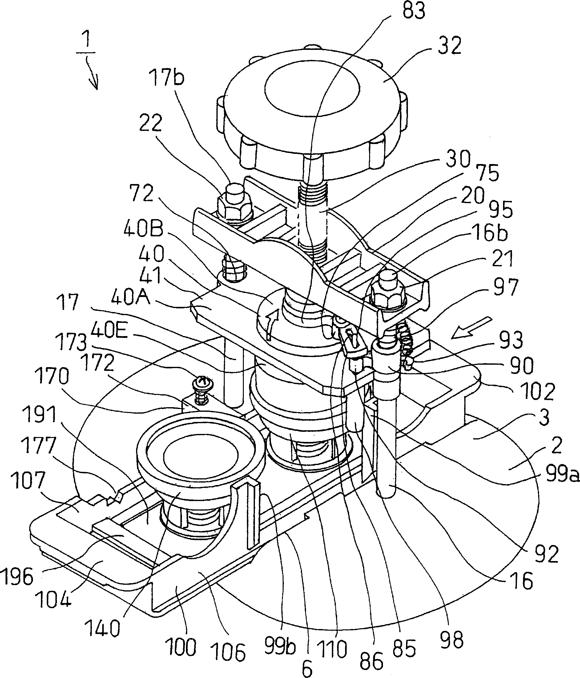
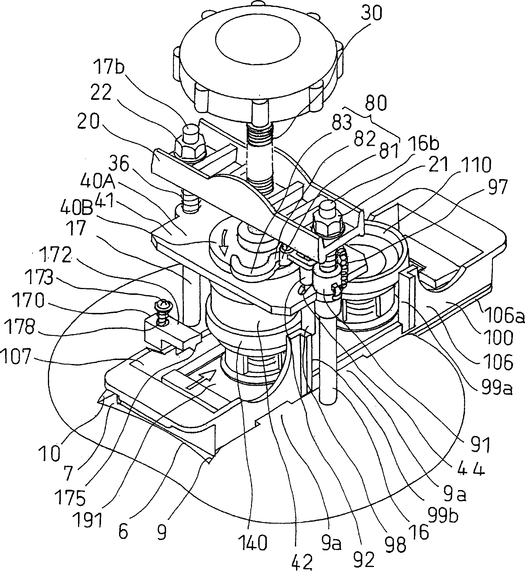
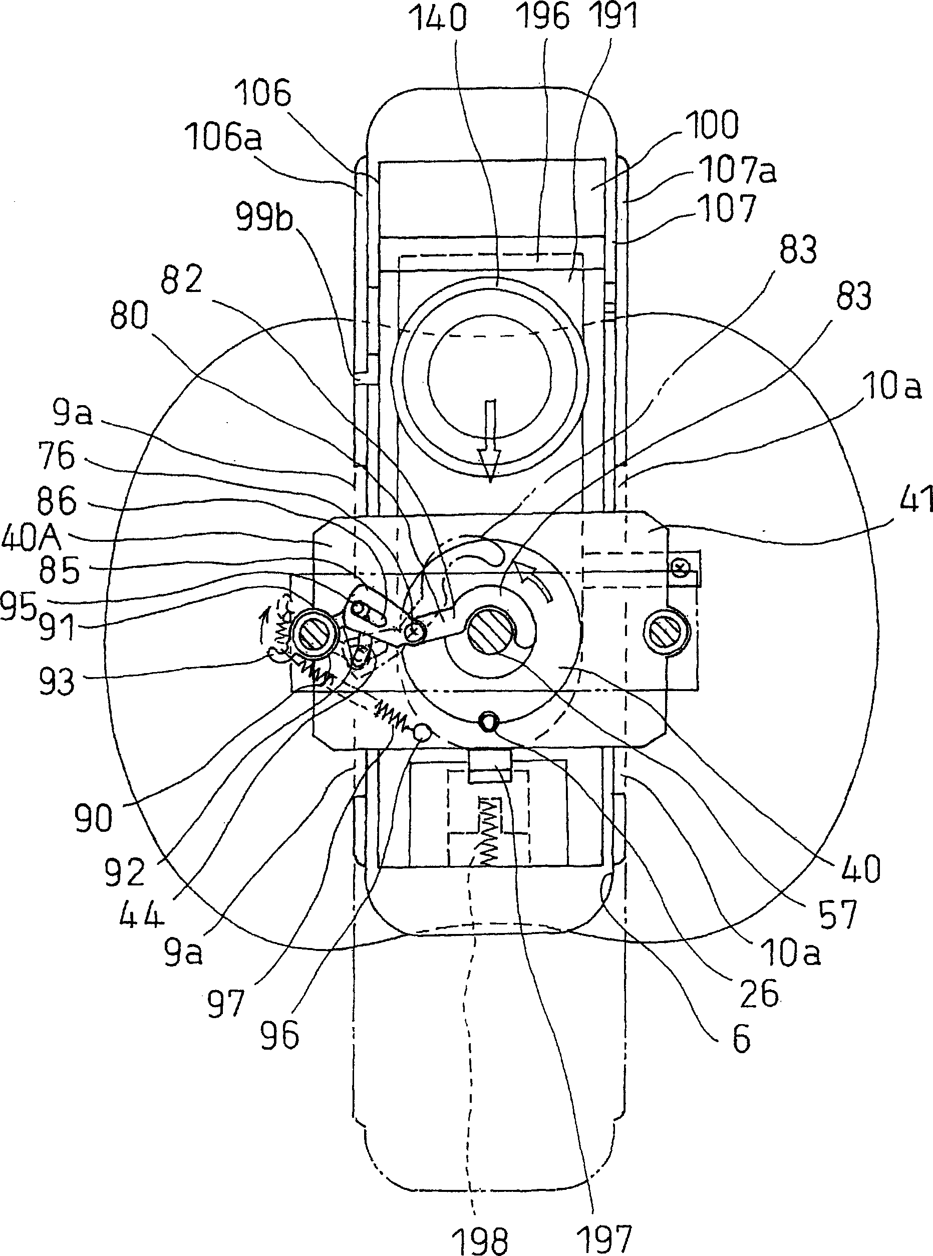
[0146] refer to Figure 1 to Figure 9 One embodiment of the emblem manufacturing apparatus according to the present invention will be described. figure 1 is an overall perspective view of the emblem manufacturing apparatus according to the present invention. figure 2 is description figure 1 Overall stereogram of the action. image 3 is description figure 1 An overall top view of the action. Figure 4 Yes figure 1 overall side sectional view. Figure 5 is an overall front sectional view showing the first die. Image 6 is description Figure 5 The overall front sectional view of the action. Figure 7 is an overall front sectional view showing the second die. Figure 8 is description Figure 7 The overall front sectional view of the action. Figure 9 It is a partially enlarged perspective view of the emblem manufacturing device.

[0147] The emblem manufacturing apparatus 1 is used to manufacture the following emblem, which includes: an outer cover 201 having a subst...


PUM


Abstract

A batch production device capable of simply exchanging first and second reception forms and a press form, so as to produce batches of different sizes; a polygonal batch whose surface plate is dome-wise curved and has its shape regulated; and such batch production device. A batch production device (1) comprises a slide block (100) mounted on the upper surface of a base block (2), first and second reception forms (110, 140) installed on an attaching member (191) removably attached to the slide block (100), a fixed member (20) fixed to the upper portion of the base block (2) through support pillars (16, 17), a vertically movable press shaft (30) installed on the fixed member (20), a press form (40) magnetically removably attached to the lower end of the press shaft (30) and adapted to be joined to the first and second reception molds (110, 140) so as to produce a batch (200), and an operating means (32) for operating the press shaft (30).

Description

technical field [0001] The present invention relates to an emblem and an emblem manufacturing device for manufacturing the emblem. The emblem has an outer cover and a back cover, and the outer cover is fitted to the back by bending the periphery of the outer cover and pressing it to the periphery of the back cover. cover. Background technique [0002] In the prior art, the emblem has an outer cover and a back cover, wherein the outer cover includes a substantially circular surface panel and a periphery extending downward from the surface panel, and the back cover includes a generally circular back panel and a The periphery of the square extension, the design paper set on the outer cover and the surrounding of the transparent cover are sandwiched between the periphery of the outer cover and the periphery of the back cover, and then the periphery of the outer cover is bent and pressed to the back. on the periphery of the cover, so that the periphery of the outer cover abuts a...

Claims


Application Information

Patent Timeline
IPC IPC(8): A44C3/00
Inventor 三宅须香子金子健儿小岛香织桃井由贵枝风见敬一菊地宪悦田村光雄小川岩吉
Owner BANDAI CO LTD
Why Eureka
Try Eureka