Winding device for removing cut binding material

The technology of a coiling device and a receiving part is applied in the field of a coiling device for taking away the cut binding material, which can solve problems such as hindering unbundling

Inactive Publication Date: 2006-03-29
VOITH PATENT GMBH
View PDF1 Cites 7 Cited by
  • Summary
  • Abstract
  • Description
  • Claims
  • Application Information

AI Technical Summary

Problems solved by technology

Bundling materials made of plastic may also tend to unwind again after winding to the extent that unbundling is impeded

Method used


Image

  • Winding device for removing cut binding material
  • Winding device for removing cut binding material
  • Winding device for removing cut binding material

Examples


Embodiment Construction

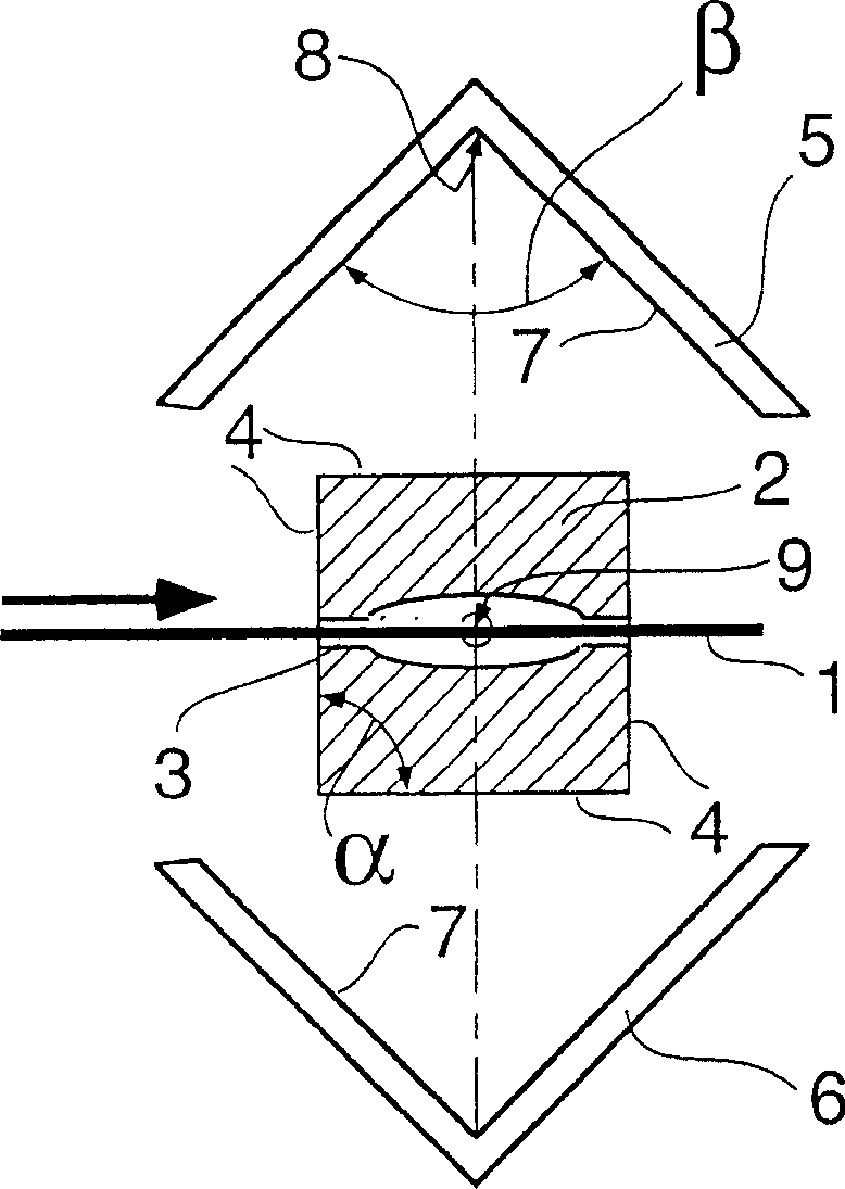
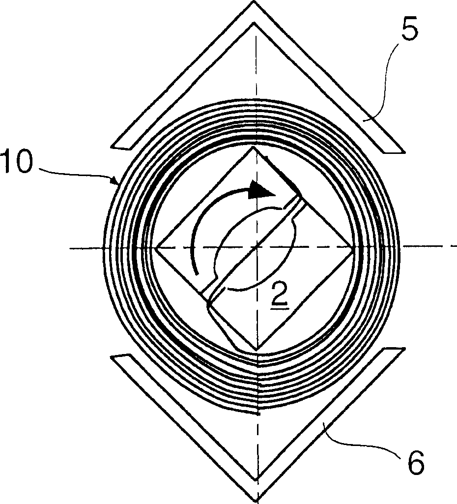
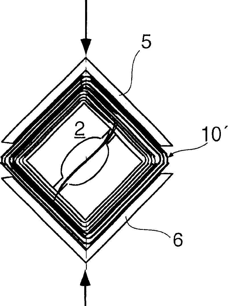
[0016] Figure 1a - 1d shows the components of the coiling device of the invention and the four main stages of its operation. The receptacle part 2 is placed with its winding surface 4 between the two extrusion parts 5 and 6 . Cutting off, loosening and slowly pulling out the binding material on the package is not shown in the figure. Next, the binding material is delivered to a suitable position facing the take-up device. exist Figure 1a In the state shown, the binding material 1 has been fed into the receiving groove 3 of the receiving element 2 . In this operating state, the two pressing parts 5 and 6 are at a greater distance from the receiving part 2, so that the binding material to be wound can assume the function of a guide. The inner surfaces of the pressing parts 5 and 6 respectively form a side wall opening toward the receiving part 2 at an included angle β=90°. The ridge line of the angle runs parallel to the axis of rotation 9 . Here, the cross section of the ...


PUM

PropertyMeasurementUnit
thicknessaaaaaaaaaa

Abstract

In a winding device for removing cut binding material (1) (especially metal bands) from bales, comprising guide(s) for the material, a receiver (2) with a winding surface (4) and a receiving slit (3) for gripping the material (the receiver being rotatable relative to the guides) and a device for axially moving the wound product from the receiver, the winding surface has a polygonal (preferably square) cross-section, the receiver is enclosed by two spaced press parts (5, 6) movable inwards towards the receiver and the inner surface (7) of the press parts is geometrically similar or identical to part of the winding surface.

Description

technical field [0001] The invention relates to a reel suitable for removing severed binding material, in particular metal strips, from packs. Background technique [0002] Such devices are used, for example, in the paper industry. The raw material for papermaking, ie pulp or waste paper, is often supplied in compact bales bound by binding material, especially wire or strip. Such wires or strips usually have to be removed before the raw material is thereafter processed in a solvent to form an aqueous suspension. While this can be done by hand, it is dangerous and laborious. Therefore further improvement and development have been made to this type of device, by means of which the removal of the cut wires and strips can be carried out automatically and smoothly, for example a reeling device that can be used for this purpose has been disclosed by German patent specification DE 2821336C2. [0003] When using the winding head according to the invention in a baling device, the ...

Claims


Application Information

Patent Timeline
Patent Type & Authority Applications(China)
IPC IPC(8): B65B69/00B65H18/08B65H54/02B21C47/04B21C47/24B21C47/26B21C47/28B21C47/32B65BB65H18/10
CPCB21C47/04B21C47/24B21C47/26B65H2701/18483B65H2701/1846B65H2301/414326B65H2701/18486B65H2701/375B65H18/10B65B69/0025B21C47/323B21C47/267B21C47/28B65H2301/41429B65H75/22B65H75/28B65H75/34B65H79/00
Inventor 埃杜阿德·加班斯基埃里克·彼得斯
Owner VOITH PATENT GMBH
Why Eureka
Try Eureka