Combined service and parking brake apparatus

A parking brake, combined technology, applied in the direction of mechanical equipment, brake type, brake actuator, etc., can solve the problem of reduced parking brake force, and achieve the effect of compact configuration and consistent parking brake performance

Inactive Publication Date: 2006-04-05
ADVICS CO LTD
View PDF0 Cites 10 Cited by
  • Summary
  • Abstract
  • Description
  • Claims
  • Application Information

AI Technical Summary

Problems solved by technology

This will inevitably reduce the parking brake force

Method used


Image

  • Combined service and parking brake apparatus
  • Combined service and parking brake apparatus
  • Combined service and parking brake apparatus

Examples


Embodiment Construction

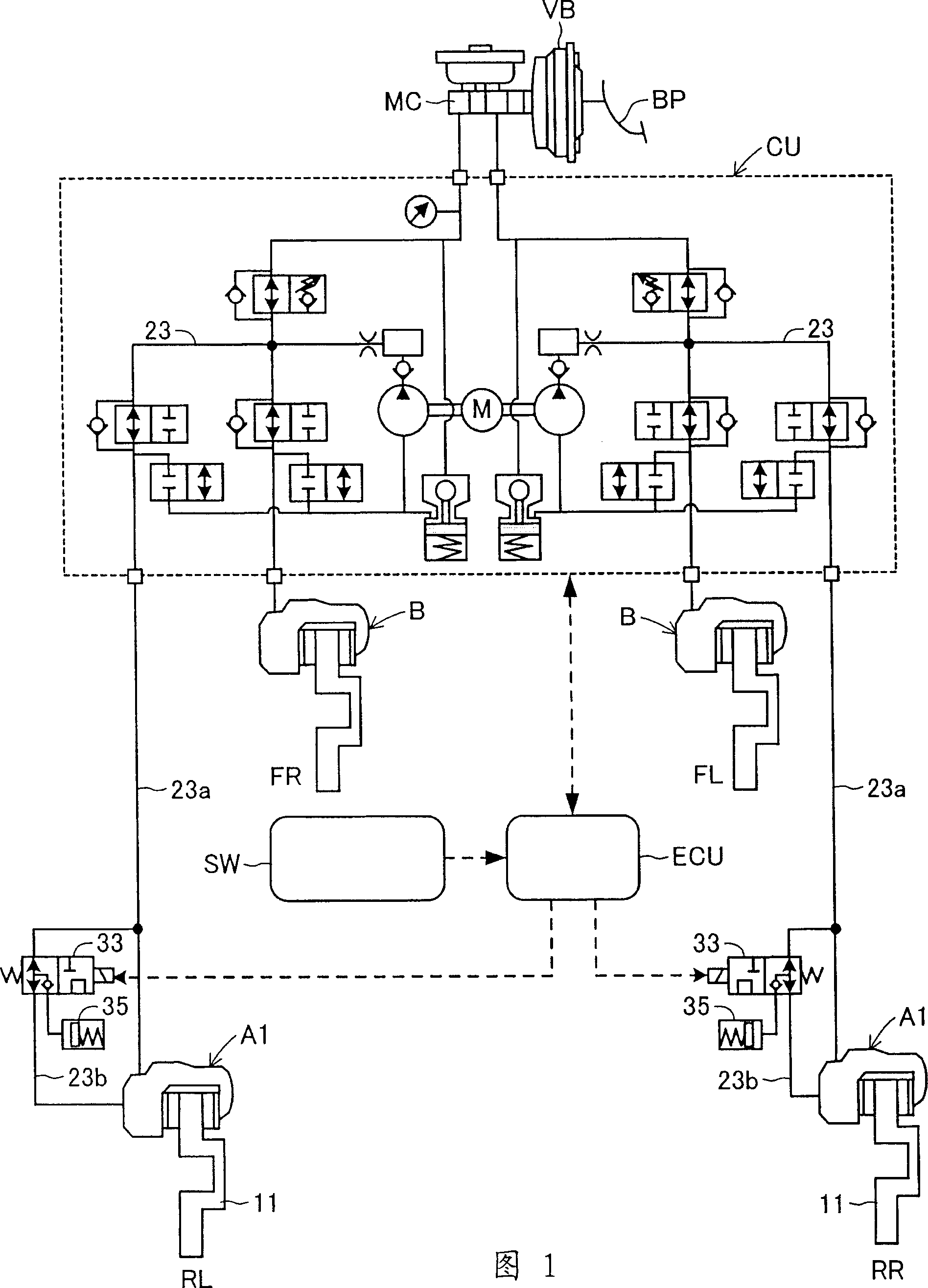
[0060] Hereinafter, embodiments of the present invention will be described in detail with reference to the accompanying drawings. Figures 1 and 2 show a first embodiment of the invention. The brake system shown in FIG. 1 includes a master cylinder MC and a brake fluid pressure control unit CU. The master cylinder can be boosted by a vacuum type booster VB in accordance with the operation of the brake pedal BP, and the brake fluid pressure control unit can Perform brake control and traction control. According to the first embodiment, the braking system uses the combined operation and parking brake device A1 for each of the left and right rear wheels RL and RR, and uses an ordinary disc for each of the left and right front wheels FL and FR. Type brake equipment B.

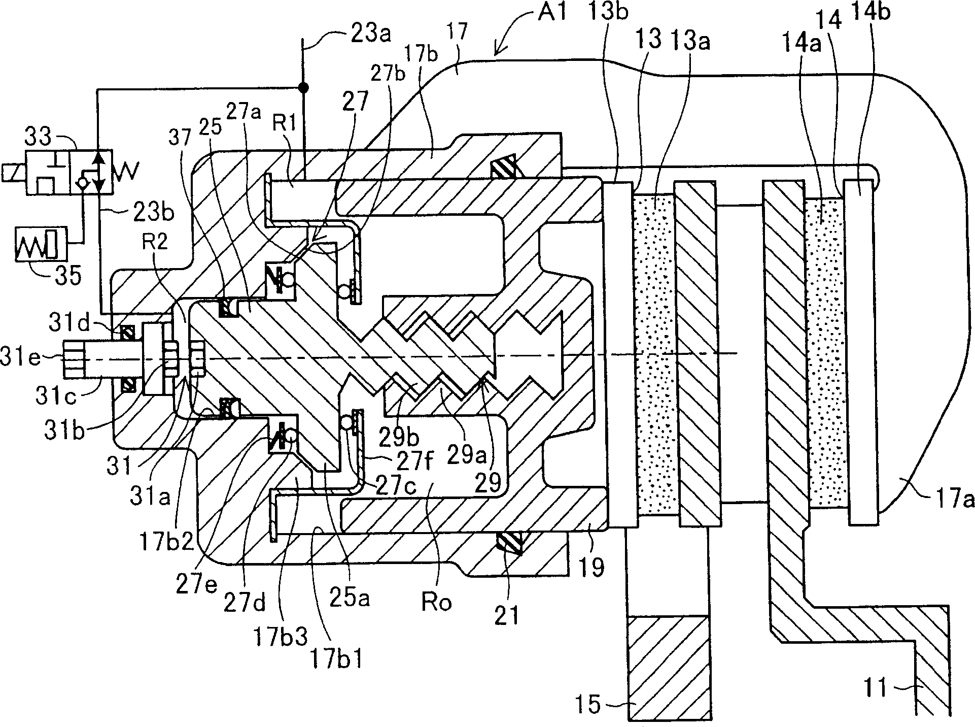
[0061] The combined operation and parking brake device A1 is a mobile caliper type disc brake to which the present invention is applied. Such as figure 2 As shown, the inner liner 13 and the outer liner 14 are mounted t...


PUM


Abstract

A combined service and parking brake apparatus includes a piston which forms a hydraulic chamber within a cylinder portion; a brake lining which, when pressed by the piston, brakes rotation of a disc rotor; a second piston which divides the hydraulic changer into a first hydraulic chamber and a second hydraulic chamber; a friction clutch which allows rotation of the second piston when the second piston is held at its home position and which disables rotation of the second piston when the second piston moves by a predetermined distance toward the second hydraulic chamber; an adjuster including an internal-thread portion and an external-thread portion and adapted to adjust the clearance between the pistons in accordance with the amount of wear of the brake lining; and a changeover valve for establishing and shutting off the communication between the first hydraulic chamber and the second hydraulic chamber.

Description

Technical field [0001] The present invention relates to a combined operation and parking brake device, which can be used as a vehicle braking device, capable of using brake fluid pressure to generate braking force not only when the device is used as a running brake but also when the device is used as a parking brake, and The device is configured so that when the device is used as a parking brake, after the braking force is generated, the device is mechanically locked to maintain the braking force. Background technique [0002] This type of combined operation and parking brake device is disclosed in, for example, Japanese PCT Patent Publication No. 2000-504811. The combined operation and parking brake device shown in Figure 4 in the publication includes: a piston placed in a cylinder in a manner that cannot rotate around the cylinder axis but can move along the cylinder axis to form a hydraulic chamber inside the cylinder; When the piston moves under the pressure of the brake flui...

Claims


Application Information

Patent Timeline
Patent Type & Authority Applications(China)
IPC IPC(8): F16D65/20F16D65/18F16D65/54F16D65/66
Inventor 桥田浩一东村英昭大庭大三神谷雅彦酒井守治村山隆
Owner ADVICS CO LTD
Why Eureka
Try Eureka