

Belt, magnetic roller, method for producing thereof, and image forming apparatus using the same
A technology of an imaging device and a magnetic roller, which is applied to an electrical recording process using a charge pattern, equipment and instruments for an electrical recording process applying a charge pattern, etc., can solve problems such as insufficient solution of adverse effects, and achieve reduction in non-uniformity. , to ensure the effect of uniformity
- Summary
- Abstract
- Description
- Claims
- Application Information
AI Technical Summary
Problems solved by technology
Method used
Image

Examples
Embodiment 1
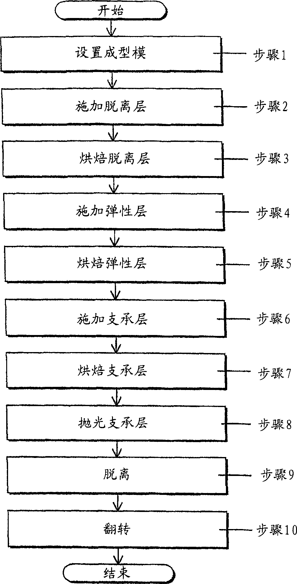
[0094] The method for producing the fixing belt according to Embodiment 1 of the present invention includes:
[0095] Applying a release layer including a fluoropolymer to a mold surface of the molding mold;
[0096] The release layer applied by baking;
[0097] Applying an elastic layer to one surface of the release layer, and the surface of the release layer is opposite to the mold surface when viewed from the release layer;
[0098] The elastic layer applied by baking;
[0099]Applying a support layer including a heat-resistant synthetic resin to one surface of the elastic layer, and the surface of the elastic layer is opposite to the mold surface when viewed from the elastic layer;
[0100] Support layer applied by baking;
[0101] Remove the unevenness of the support layer; and
[0102] The release layer, elastic layer and supporting layer are separated from the mold surface.
[0103] image 3 It is a flowchart showing each process according to Embodiment 1 of the present in...
Embodiment 2
[0143] The method for producing the fixing belt according to Embodiment 2 of the present invention includes:
[0144] Applying a release layer including a fluoropolymer to a mold surface of the molding mold;
[0145] The release layer applied by baking;
[0146] Applying an elastic layer to one surface of the release layer, and the surface of the release layer is opposite to the mold surface when viewed from the release layer;
[0147] The elastic layer applied by baking;
[0148] Applying a support layer including a heat-resistant synthetic resin to one surface of the elastic layer, and the surface of the elastic layer is opposite to the mold surface when viewed from the elastic layer;
[0149] Dry the applied support layer;
[0150] Remove the unevenness of the supporting layer;
[0151] The support layer applied by baking; and
[0152] The release layer, elastic layer and support layer are separated from the mold surface.
[0153] Hereinafter, in this embodiment, the difference...
Embodiment 3
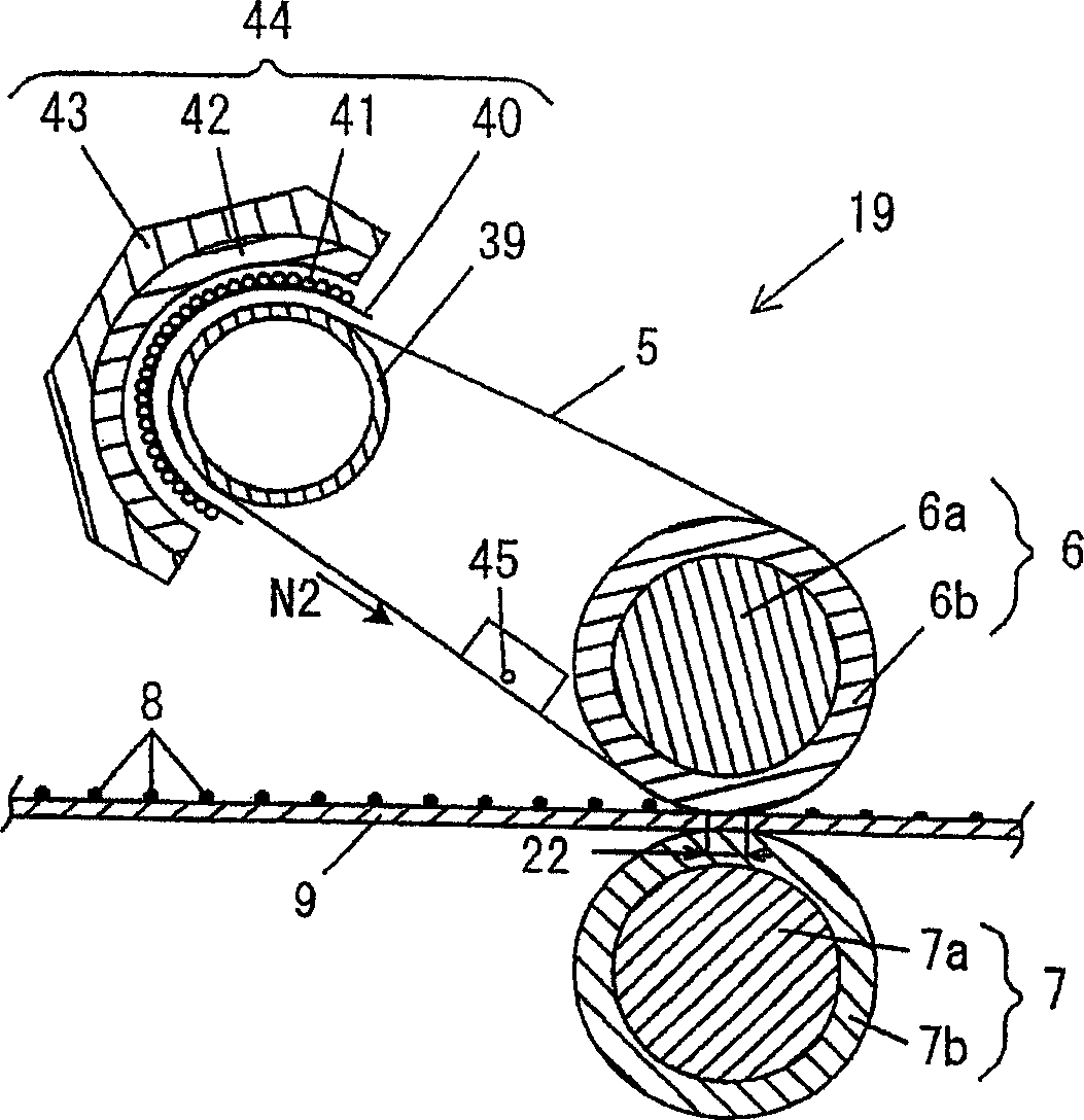
[0167] In Embodiments 1 and 2, the present invention is applied to the fixing belt. However, the present invention can also be applied to a transfer belt as described below.
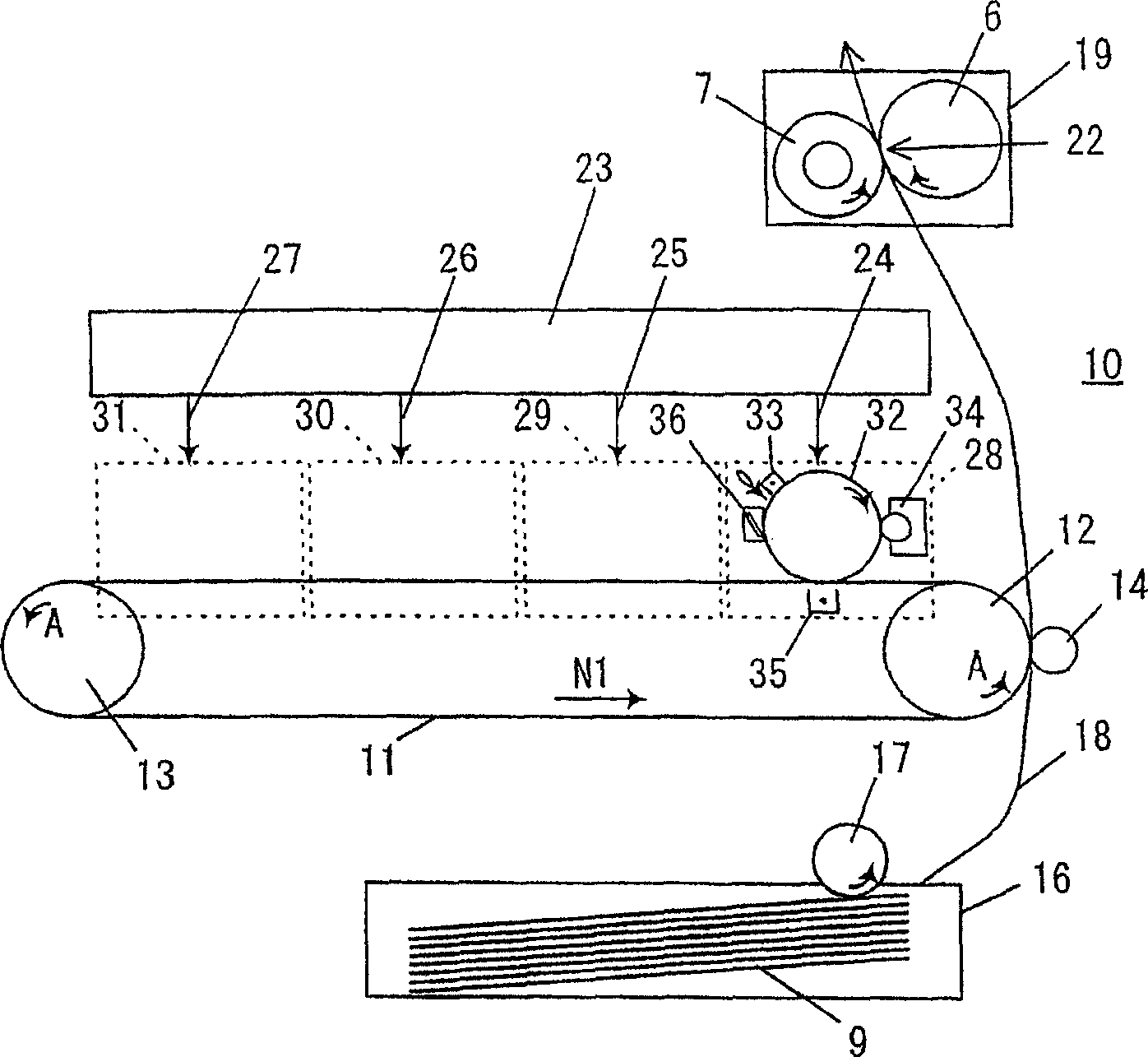
[0168] Below, will refer to Picture 10 And FIG. 11 describes an imaging apparatus according to Embodiment 3 of the present invention. Picture 10 It is a cross-sectional view of an image forming apparatus according to Embodiment 3 of the present invention.
[0169] Picture 10 The imaging device in is compatible with figure 1 Tandem system of similar imaging devices. However, the present invention is not limited to a tandem system of imaging devices, and can be applied to various imaging devices, such as a monochrome imaging device or an imaging device adopting a surface continuous system.
[0170] In this embodiment, the imaging device can form a medium (width, 197 mm) suitable for A4 size. In addition to the other aspects indicated, a length of 210-230mm (its longitudinal and Picture 10 The paper is pe...
PUM
 Abstract
Description
Claims
Application Information