

Near drill local low pressure drilling tool
A drilling tool and near-bit technology, which can be used in drill bits, drilling equipment, earth-moving drilling, etc.
- Summary
- Abstract
- Description
- Claims
- Application Information
AI Technical Summary
Problems solved by technology
Method used
Image

Examples
Embodiment Construction
[0008] The present invention will be further described now in conjunction with the accompanying drawings of the description.
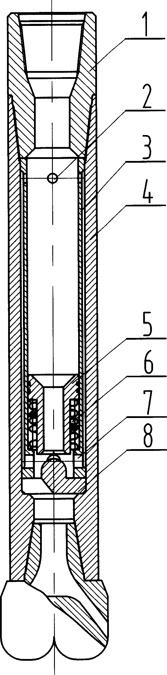
[0009] When using the present invention for hydraulic pulse low-pressure drilling construction, the casing [4] is hollow cylindrical, with threads processed at both ends, and the limit plug [8] processed with a flow channel is loaded into the lower end of the casing [4] , the inner tube [3] is hollow cylindrical, and the upper and lower ends are respectively processed with an upper back pressure hole [2] and a lower back pressure hole [7]. The spool valve [5] of the center flow channel is loaded into the inner lower end of the inner tube [3] sequentially, wherein the spool valve [5] and the inner tube [3] are sealed, and the lower end of the spool valve [5] extends into the spool valve spring [ 6], the shoulder of the spool valve [5] is in contact with the upper end surface of the spool valve spring [6], and then the inner tube [3] is fitted into the h...
PUM
 Abstract
Description
Claims
Application Information