

Space robot paw
A space robot and gripper technology, applied in the field of robotics, can solve the problems of not uniquely determining the final grasping position, easy to lose the target, and small capture range of the gripper. Effect
- Summary
- Abstract
- Description
- Claims
- Application Information
AI Technical Summary
Problems solved by technology
Method used
Image

Examples
specific Embodiment approach 1
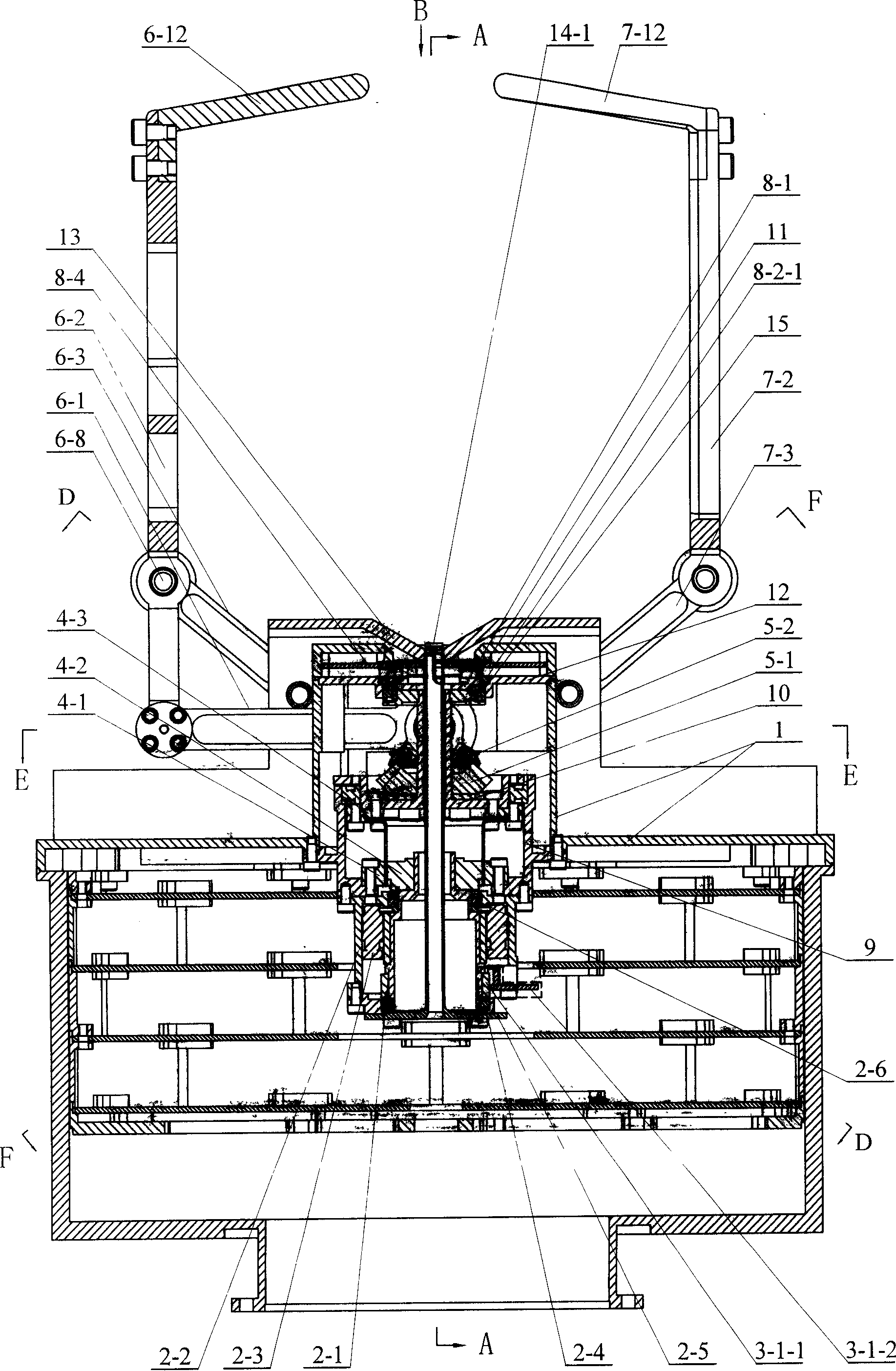
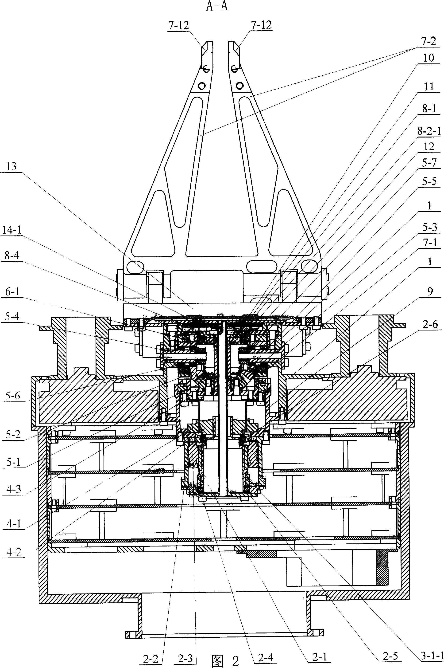
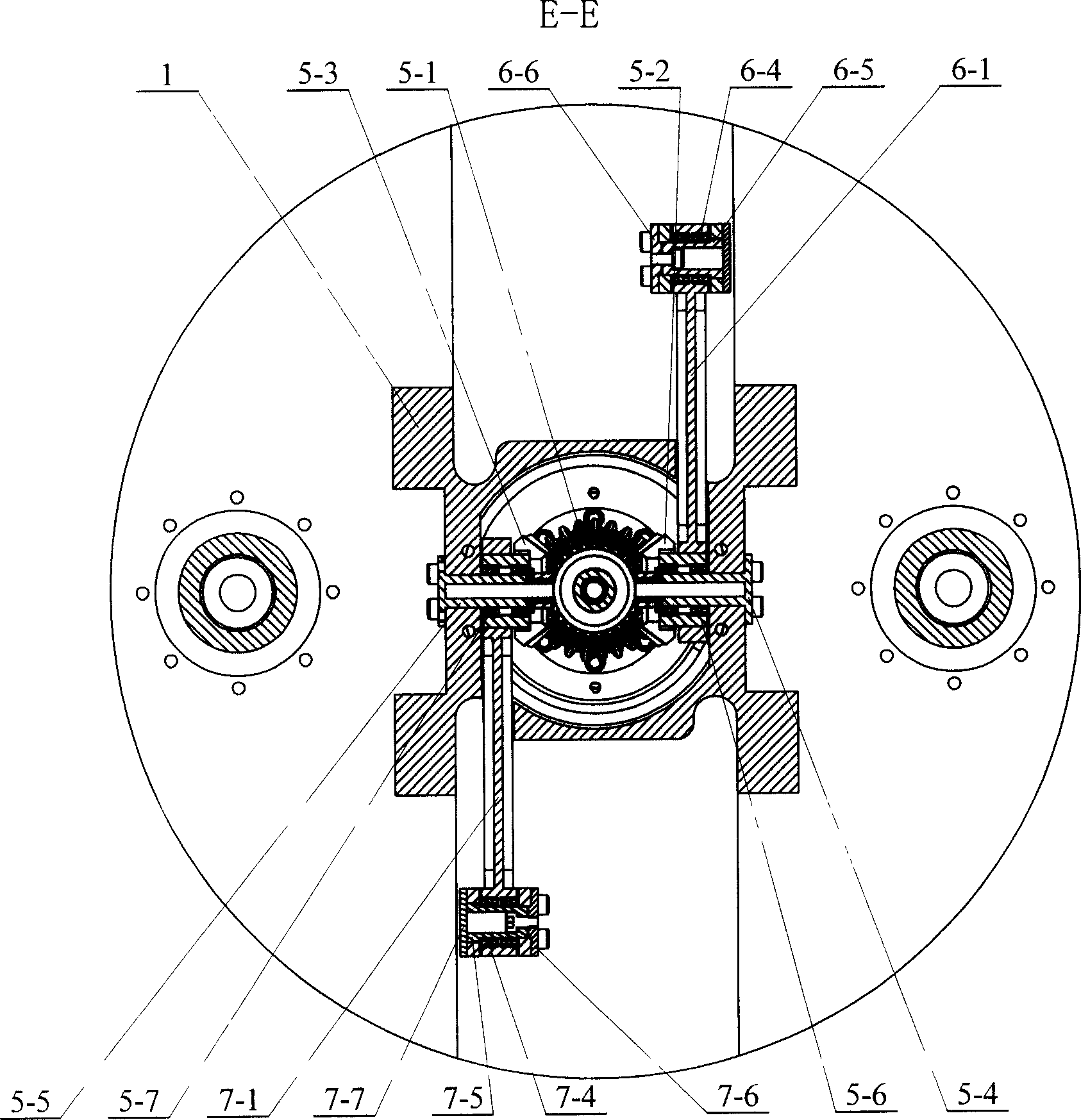
[0006] Specific implementation mode one: combine figure 1 ,figure 2, Figure 5 , Fig. 7 illustrates this embodiment, and this embodiment is made up of housing 1, motor drive unit, motor position sensor, harmonic speed reducer component, gear transmission, single finger four-bar linkage mechanism, two-finger four-bar linkage mechanism, finger position sensor , support sleeve 9, drive flange 10, shaft end flange 11, end cover plate 12, V-shaped positioning groove 13, and contact sensor; the magnetic ring 3-1-1 in the motor position sensor is fixed in the motor drive device On the motor rotating shaft 2-1, the motor housing 2-2 in the motor driving device is fixedly connected with the support sleeve 9, and the support sleeve 9 is fixedly connected with the rigid wheel 4-1 in the harmonic reducer part, and the harmonic reducer part The wave generator 4-2 is fixedly installed on the motor shaft 2-1, the flexspline ring 4-3 in the harmonic reducer part is fixedly connected with the...
specific Embodiment approach 2
[0008] Specific implementation mode two: combination figure 1 , Fig. 2 illustrates the present embodiment, the motor position sensor of the present embodiment is made up of magnetic encoder and the intrinsic digital Hall element of motor itself; Magnetic encoder is made up of magnetic ring 3-1-1, magnetic ring detection circuit 3-1- 2 components; the magnetic ring 3-1-1 is fixedly installed on the outer circumferential end face of the motor shaft 2-1, and the outer side of the magnetic ring 3-1-1 is equipped with a magnetic ring detection circuit 3- which is fixedly connected with the motor casing 2-2 1-2. The motor position sensor is used, and the motor position detection system is composed of a magnetic encoder and a digital hall element inherent in the motor itself. The magnetic ring detection circuit 3-1-2 is installed on the motor shell 2-2 to record the rotation position of the motor. Other components and connections are the same as those in the first embodiment.
specific Embodiment approach 3
[0009] Specific implementation mode three: combination figure 1 , Fig. 2 illustrates the present embodiment, and the motor driving device of the present embodiment is a DC brushless motor; Described DC brushless motor is made up of motor rotating shaft 2-1, motor casing 2-2, motor stator 2-3, the first motor Bearing 2-4, bearing cover 2-5, second motor bearing 2-6 are composed; motor stator 2-3 is fixedly connected with motor casing 2-2, and motor shaft 2-1 and motor shaft 2 are housed in motor stator 2-3 The first motor bearing 2-4 is housed between -1 and the motor housing 2-2, the first motor bearing 2-4 is positioned by the bearing cover 2-5, the bearing cover 2-5 is fixedly connected with the motor housing 2-2, and the motor A second motor bearing 2-6 is installed between the rotating shaft 2-1 and the motor casing 2-2, and the motor casing 2-2 is fixedly connected with the support sleeve 9. It adopts DC brushless motor to facilitate its control. Other components and co...
PUM
 Abstract
Description
Claims
Application Information